In the world of microcontrollers, Arduino has carved out a reputation for creating user-friendly and versatile boards. The Arduino GIGA R1 WiFi, their latest offering, is no exception. Designed for ambitious creators, this board promises high performance with its STM32H7 processor, while also offering the convenience of built-in WiFi.
In this article, we dive deep into the capabilities and features of the GIGA R1, examining its potential for various applications. Whether you’re a seasoned Arduino veteran or a curious newcomer, this review aims to provide you with a comprehensive understanding of what the Arduino GIGA R1 has to offer.
Arduino GIGA R1 Review:
Specifications
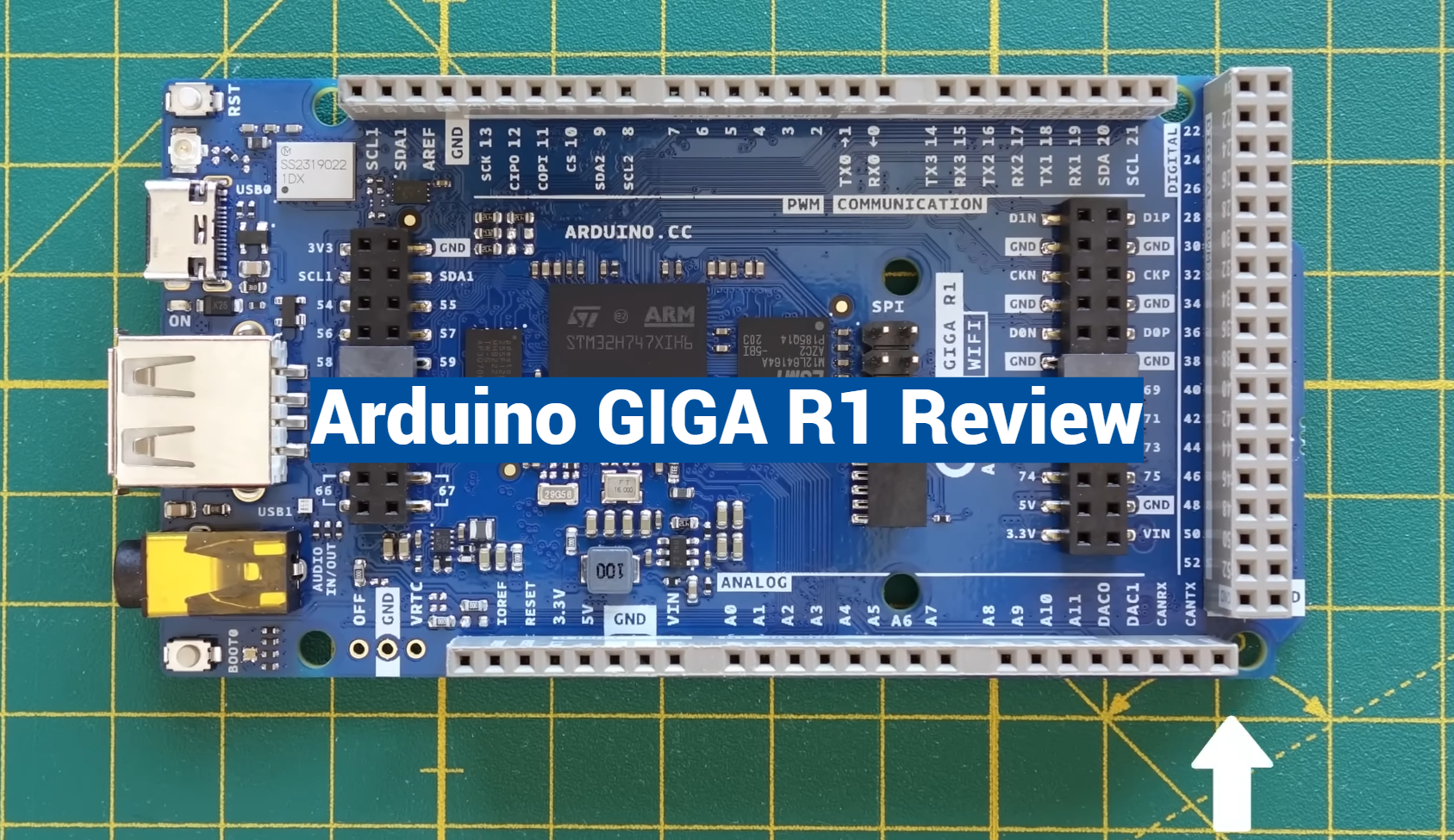
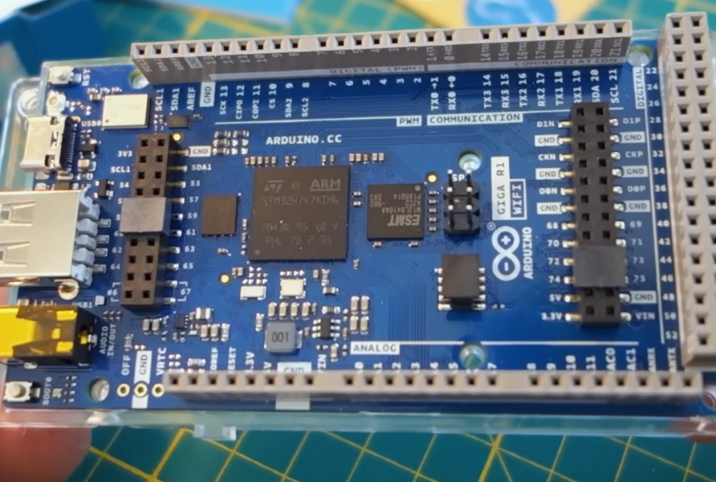
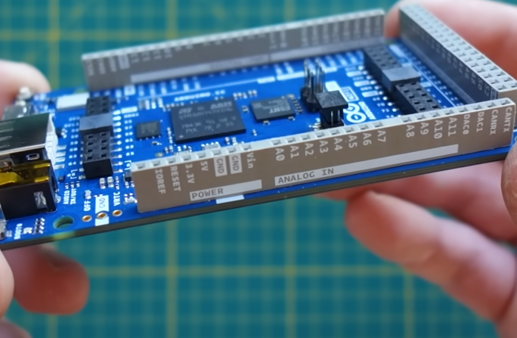
The GIGA R1 comes packed with high-end specifications that position it as a top-tier choice for developers. It is powered by a dual-core microcontroller (STM32H747XI) and a Murata 1DX module for wireless communication. The board also boasts a large number of GPIOs and extra pins, a 3.5mm audio jack, USB interfaces, and specialty pins.
Size
The GIGA R1 maintains a compact form factor that is typical of Arduino boards. Despite the wealth of features and functionalities it carries, the GIGA R1 manages to keep a relatively small footprint, making it suitable for various projects where space is a constraint.
Processor
At the heart of the GIGA R1 is the STM32H747XI microcontroller. This dual-core chip combines an ARM Cortex-M7 and Cortex-M4, both capable of running up to 480 MHz and 240 MHz respectively. This processor setup allows for efficient task management and high-speed processing, thus enabling complex applications.
Wi-Fi & Bluetooth
The Arduino GIGA R1 houses a Murata 1DX module that facilitates wireless communication. This module supports Wi-Fi 802.11b/g/n and Bluetooth 5.0, allowing for high-speed internet connectivity and short-range wireless communication respectively.
Specialty Pins
The GIGA R1 has an array of specialty pins that offer additional functionalities. These include I2C, SPI, and UART interfaces, which are useful for communicating with various peripherals and other microcontrollers.
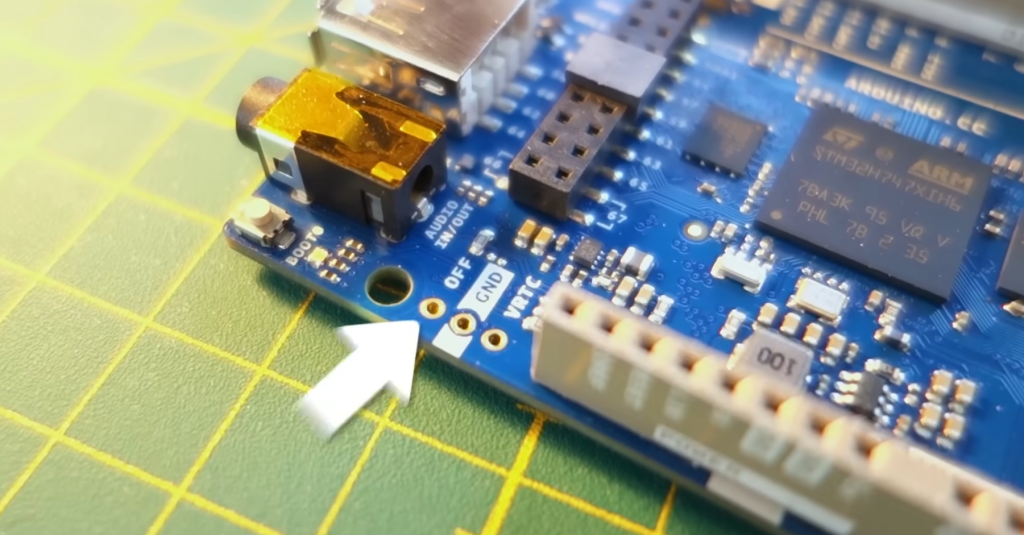
3.5mm Audio Jack and USB Interfaces
For audio applications, the GIGA R1 provides a 3.5mm audio jack. It also has multiple USB interfaces, including USB-C for power and programming, and USB-A for host functionality. These features make the GIGA R1 a versatile board suitable for a variety of projects.
Microcontroller (STM32H747XI)
The dual-core STM32H747XI microcontroller is a significant highlight of the GIGA R1. It offers a blend of high performance and energy efficiency, making it an excellent choice for both simple and complex applications. The microcontroller also supports a wide range of interfaces, further enhancing the versatility of the GIGA R1.
Wireless Communication (Murata 1DX)
The Murata 1DX module in the GIGA R1 ensures reliable wireless communication. Whether you need Wi-Fi for internet connectivity or Bluetooth for short-range communication, the Murata 1DX module has you covered.
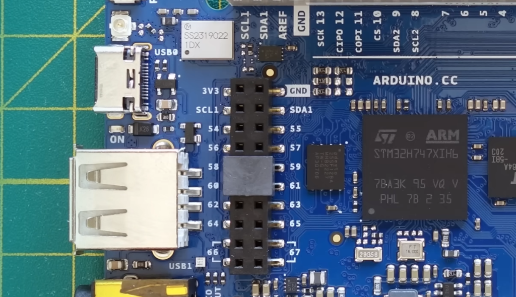
Hardware Ports And Communication
Apart from the standard digital I/O pins, the GIGA R1 comes with several hardware communication ports. These include SPI, I2C, and UART, which facilitate communication with a wide range of devices and peripherals.
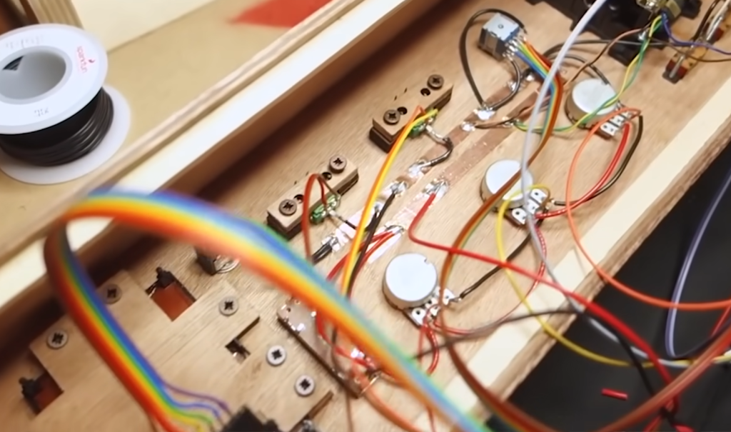
GPIOs and Extra Pins
The Arduino GIGA R1 boasts an impressive number of GPIO pins, giving developers ample flexibility when designing their projects. Additionally, the board comes with extra pins that can be used for various functions such as interrupts, PWM, and more.
Connectors
The GIGA R1 comes with a number of connectors, including USB-C for power and programming, USB-A for host functionality, and a 3.5mm audio jack. These connectors enhance the usability of the board and make it a versatile choice for various applications.
Pinout
The pinout of the GIGA R1 is well-organized and clearly labeled, making it easy for developers to connect peripherals and other devices. The board supports a variety of interfaces, including digital I/O, analog input, PWM, SPI, I2C, and UART, further enhancing its versatility [2].
Application Scenarios:
The Arduino GIGA R1 is designed with versatility in mind. Its wide range of features and powerful processing capabilities make it suitable for a variety of application scenarios.
Robotic Applications
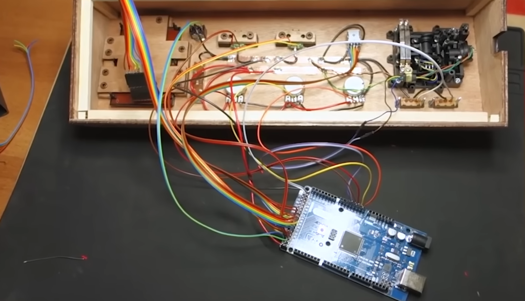
The dual-core STM32H747XI microcontroller, ample GPIO pins, and a variety of communication interfaces make the GIGA R1 an excellent choice for robotic applications. Whether you’re building a complex multi-limbed robot or a simple line follower, the GIGA R1 has the processing power and flexibility to handle the task. Additionally, the onboard Wi-Fi and Bluetooth can be used for remote control or even inter-robot communication.
Upgrading 3D Printers
3D printers require precise control of stepper motors, temperature sensors, and often, a user interface. The GIGA R1, with its high-speed microcontroller and wealth of I/O options, is more than capable of handling these tasks. Moreover, the Wi-Fi connectivity allows for remote monitoring and control of the printer, providing a significant upgrade to many existing 3D printer models.
IoT Applications
The Internet of things (IoT) is all about connected devices, and the GIGA R1 is well-equipped for this. The Murata 1DX module provides Wi-Fi and Bluetooth connectivity, allowing the GIGA R1 to communicate with other devices and the internet. Whether you’re designing a smart home system, an industrial IoT setup, or a wearable device, the GIGA R1 has the features you need.
Hi-Fi Audio Processing
With a 3.5mm audio jack and support for I2S digital audio, the GIGA R1 is a great choice for high-fidelity audio processing applications. Whether you’re building a digital audio workstation, a synthesizer, or a sound effects generator, the GIGA R1 can handle the job.
Computer Vision (CV)
The powerful STM32H747XI microcontroller and the large number of GPIOs make the GIGA R1 ideal for computer vision applications. Whether it’s a security camera with face recognition, a drone with obstacle avoidance, or an automated inspection system, the GIGA R1 has the processing power to analyze video in real time and make intelligent decisions based on what it sees [3].
Summing up, the Arduino GIGA R1 is a versatile and powerful board that can be used in a wide array of applications. Its robust hardware and extensive connectivity options make it a go-to choice for developers, hobbyists, and professionals alike.
Whether you’re a beginner looking to dip your toes into the world of electronics or a seasoned professional working on a complex project, the GIGA R1 is a board worth considering.
Using Arduino GIGA R1:
1) Installing the Boards Manager:
- Open the Arduino IDE on your computer;
- Navigate to Tools > Board > Boards Manager;
- In the Boards Manager, search for the Arduino GIGA Boards;
- Click on the result and then click on install;
Once the installation is complete, you should be able to select the Arduino GIGA R1 from the list of available boards. This is a crucial step as it allows the IDE to understand the specifications and capabilities of the GIGA R1 board.
2) Resolving the LINUX DFU Problem
If you’re facing issues with the LINUX DFU (Device Firmware Update), it might be due to a problem with the firmware of the WiFi module on the GIGA R1. There have been instances where users were not able to reinstall the WiFi firmware.
If you encounter this issue, running QSPIFormat might help. If the problem persists, it would be best to reach out to the Arduino support team or community for further assistance.
Remember, always ensure that your Arduino IDE is up-to-date to avoid any compatibility issues with the board and the software.
3) Using the Real-Time Clock
4) Battery Backup
Many RTC modules come with a slot for a backup battery. This allows the RTC to keep track of time even when the main power is disconnected. To provide battery backup:
- Purchase a suitable coin cell battery (usually a CR2032);
- Insert the battery into the battery holder on the RTC module;
- Connect the RTC module to the Arduino GIGA R1;
Now, even if the main power supply is interrupted, the RTC will continue to keep time.
5) Manual RTC Code
To set and read time from the RTC, you would need to write some code in the Arduino IDE.
Here’s a simple example that uses the DS1307 RTC module:
#include <Wire.h>
#include “RTClib.h”
RTC_DS1307 rtc;
void setup () {
Wire.begin();
rtc.begin();
if (! rtc.isrunning()) {
rtc.adjust(DateTime(__DATE__, __TIME__));
}
}
void loop () {
DateTime now = rtc.now();
Serial.print(now.year(), DEC);
Serial.print(‘/’);
Serial.print(now.month(), DEC);
Serial.print(‘/’);
Serial.print(now.day(), DEC);
Serial.print(‘ ‘);
Serial.print(now.hour(), DEC);
Serial.print(‘:’);
Serial.print(now.minute(), DEC);
Serial.print(‘:’);
Serial.print(now.second(), DEC);
Serial.println();
delay(1000);
}
This code sets the RTC to the date and time at which the code was compiled and then prints the current date and time every second [4].
6) WiFi RTC Code
If you want to set the time using WiFi (for example, by connecting to an NTP server), you can use the WiFi capabilities of the Arduino GIGA R1.
Here’s a simple example:
#include <WiFi.h>
#include “RTClib.h”
const char* ssid = “your_SSID”; // your network SSID (name)
const char* password = “your_PASSWORD”; // your network password
RTC_DS1307 rtc;
void setup () {
Wire.begin();
rtc.begin();
WiFi.begin(ssid, password);
while (WiFi.status() != WL_CONNECTED) {
delay(1000);
}
configTime(0, 0, “pool.ntp.org”);
setRTCTime();
}
void loop () {
DateTime now = rtc.now();
Serial.print(now.year(), DEC);
Serial.print(‘/’);
Serial.print(now.month(), DEC);
Serial.print(‘/’);
Serial.print(now.day(), DEC);
Serial.print(‘ ‘);
Serial.print(now.hour(), DEC);
Serial.print(‘:’);
Serial.print(now.minute(), DEC);
Serial.print(‘:’);
Serial.print(now.second(), DEC);
Serial.println();
delay(1000);
}
void setRTCTime() {
struct tm timeinfo;
if(getLocalTime(&timeinfo)){
rtc.adjust(DateTime(timeinfo.tm_year + 1900, timeinfo.tm_mon + 1, timeinfo.tm_mday, timeinfo.tm_hour, timeinfo.tm_min, timeinfo.tm_sec));
}
}
This code connects to your WiFi network, gets the current time from an NTP server, sets the RTC to this time, and then prints the current date and time every second.
Please note that these are just example codes and might not work perfectly with your specific setup. Always make sure to adjust the code to match the specifics of your hardware configuration. Also, don’t forget to replace “your_SSID” and “your_PASSWORD” with your actual WiFi SSID and password.
Working with USB-A:
Working with USB drives on the Arduino GIGA R1 can be accomplished using the USB Host Library. This library allows for reading and writing files to a USB drive formatted with the FAT32 file system.
Here’s how you can perform various operations:
USB Drive with FAT32
To use a USB drive with the Arduino GIGA R1, it needs to be formatted with the FAT32 file system. You can do this using the formatting tools available in most operating systems.
1) In Windows:
- Insert the USB drive into your computer;
- Open “This PC” and right-click on the USB drive;
- Select “Format”;
- In the “File system’ dropdown menu, select “FAT32”;
- Click “Start” [5];
2) In macOS:
- Open Disk Utility;
- Select the USB drive from the list of drives on the left;
- Click “Erase”;
- For the format, choose “MS-DOS (FAT)”;
- Click “Erase” again;
Read USB Directory
Once the USB drive is properly formatted and connected to the GIGA R1, you can read the directory using the USB Host Library.
Here’s an example of how you can do this:
#include <USBHost_t36.h>
USBHost myusb;
USBHub hub1(myusb);
MassStorageDriver msd(myusb);
void setup() {
Serial.begin(9600);
while (!Serial && millis() < 4000) ;
myusb.begin();
}
void loop() {
myusb.Task();
if (msd.available()) {
msd.ls();
}
}
This code will print the names of all files and folders in the root directory of the USB drive to the serial monitor.
Write File to USB Device
To write a file to the USB device, you can use the File and FileSystem classes provided by the USB Host Library.
Here’s an example:
#include <USBHost_t36.h>
USBHost myusb;
USBHub hub1(myusb);
MassStorageDriver msd(myusb);
FileSystem_t36 fs(msd);
void setup() {
Serial.begin(9600);
while (!Serial && millis() < 4000) ;
myusb.begin();
}
void loop() {
myusb.Task();
if (msd.available()) {
File file = fs.open(“test.txt”, FILE_WRITE);
if (file) {
file.println(“Hello, world!”);
file.close();
}
}
}
This code will create a file named test.txt in the root directory of the USB drive and write the string “Hello, world!” to it [6].
Read File from USB Device
To read a file from the USB device, you can use the File and FileSystem classes as well. Here’s an example:
#include <USBHost_t36.h>
USBHost myusb;
USBHub hub1(myusb);
MassStorageDriver msd(myusb);
FileSystem_t36 fs(msd);
void setup() {
Serial.begin(9600);
while (!Serial && millis() < 4000) ;
myusb.begin();
}
void loop() {
myusb.Task();
if (msd.available()) {
File file = fs.open(“test.txt”);
if (file) {
while (file.available()) {
Serial.write(file.read());
}
file.close();
}
}
}
This code will open the file named test.txt and print its contents to the serial monitor.
Please note that these are just example codes and might not work perfectly with your specific setup. Always make sure to adjust the code to match the specifics of your hardware configuration.
Using the 16-bit ADCs:
The Arduino GIGA R1 board comes with a built-in 16-bit Analog-to-Digital Converter (ADC). This ADC can be used to read analog signals, such as those from sensors or potentiometers.
ADC Hookup
Here’s a basic way to connect an analog sensor to the Arduino GIGA R1:
- Connect the VCC pin of the sensor to the 3.3V or 5V output (depending on your sensor’s specifications) of the Arduino GIGA R1;
- Connect the GND pin of the sensor to any GND pin on the Arduino GIGA R1;
- Connect the signal output pin of the sensor to one of the analog input pins on the Arduino GIGA R1 (e.g., A0);
Remember that the specifics of the hookup might vary depending on the type of sensor you’re using.
ADC Sketch
To read the value from the ADC, you can use the analogRead() function in the Arduino IDE. Here’s a simple sketch that reads the value from a sensor connected to pin A0 and prints it to the serial monitor:
void setup() {
Serial.begin(9600);
}
void loop() {
int sensorValue = analogRead(A0);
Serial.println(sensorValue);
delay(1000);
}
This code will print the raw 16-bit value read from the ADC. The value will be between 0 (when the input voltage is 0V) and 65535 (when the input voltage is the same as the reference voltage). The default reference voltage is the same as the operating voltage of the board (3.3V for the Arduino GIGA R1).
If you want to convert this raw value to a voltage, you can modify the sketch like this:
void setup() {
Serial.begin(9600);
}
void loop() {
int sensorValue = analogRead(A0);
float voltage = sensorValue * (3.3 / 65535.0);
Serial.println(voltage);
delay(1000);
}
This code will print the input voltage (in volts) to the serial monitor. Please note that these are just example codes and might not work perfectly with your specific setup. Always make sure to adjust the code to match the specifics of your hardware configuration.
Using the DACs & Build a Waveform Generator:
The Arduino GIGA R1 board comes with built-in Digital-to-Analog Converters (DACs), which can be used to generate analog signals. In this case, we’ll use it to build a simple waveform generator.
Scope Hookup
To visualize the output of the DAC, you’ll need an oscilloscope. Here’s how you can hook it up:
- Connect the ground (usually black) probe of the oscilloscope to a GND pin on the Arduino GIGA R1;
- Connect the signal (usually red) probe of the oscilloscope to the DAC0 pin on the Arduino GIGA R1;
Waveform Generator Code
You can generate different types of waveforms using the analogWrite() function in the Arduino IDE.
Here’s a simple sketch that generates a sine wave:
#define DAC_PIN DAC0
void setup() {
pinMode(DAC_PIN, OUTPUT);
}
void loop() {
for (int i = 0; i < 360; i++) {
float rad = i * DEG_TO_RAD;
float sinVal = sin(rad);
int dacVal = (sinVal + 1.0) / 2.0 * 65535;
analogWrite(DAC_PIN, dacVal);
delay(1);
}
}
This code generates a sine wave by calculating the sine of the angle (in radians), scaling it to the range of the DAC (0 – 65535), and writing it to the DAC [7].
FAQ:
1. Is Arduino Giga R1 WiFi any good?
Based on the search results, the Arduino GIGA R1 WiFi is considered a powerful Arduino board. It’s specifically designed for ambitious makers, gamers, artists, and sound designers. It uses the STM32H7 processor, which is known for its high performance. The board also includes onboard WiFi. However, some users argue that it doesn’t make anything possible that wasn’t already achievable with an ESP32.
2. What is the difference between Arduino Giga and Portenta H7?
Both the Arduino Giga R1 WiFi and the Portenta H7 use the same STM32H7 dual-core microcontroller. The main difference is that the Giga R1 brings this powerful microcontroller to the larger and more accessible Mega form factor.
3. Which Arduino version is best?
The “best” Arduino version depends largely on your specific needs and requirements. For example, the Arduino Giga R1 WiFi is considered the most powerful Arduino board, making it a great choice for ambitious projects. However, simpler boards like the Arduino Uno might be better for beginners or less complex projects.
4. Which is the best Wi-Fi module for Arduino?
There are many WiFi modules available for Arduino, and the best one will depend on your specific needs. The ESP8266 and ESP32 are popular choices due to their low cost and built-in WiFi capabilities. The Arduino Giga R1 WiFi has an onboard WiFi module, which could be more convenient if you want an all-in-one solution.
5. Which Arduino has built-in Wi-Fi?
Several Arduino boards come with built-in WiFi. These include the Arduino Giga R1 WiFi, as well as the Arduino Uno WiFi, Arduino MKR WiFi 1010, and Arduino Nano 33 IoT.
6. Which Arduino IDE is most stable?
The official Arduino IDE is considered to be the most stable, as it’s maintained by the Arduino team and regularly updated with bug fixes and new features. It supports all Arduino boards and includes a wide range of built-in examples and libraries.
7. Is Arduino fast enough?
The speed of an Arduino board depends on its specific microcontroller. For example, the Arduino Giga R1 WiFi uses the STM32H7, which is a high-performance microcontroller. In general, Arduino boards should be fast enough for most hobbyist projects, but might not be suitable for applications requiring very high speed or computational power.
Useful Video: The New Arduino Giga R1 WiFi (Part 1)
References:
- https://www.tomshardware.com/news/arduino-giga-r1-wifi-controller-launches
- https://www.dfrobot.com/blog-13431.html
- https://dronebotworkshop.com/giga/
- https://www.elektor.com/arduino-giga-r1-wifi
- https://www.electromaker.io/blog/article/arduino-go-giga-with-their-latest-release
- https://www.techgoing.com/arduino-launched-giga-r1-wifi-with-76-gpio-pins/
- https://hackaday.com/tag/arduino-giga/