Did you know a single microcontroller can simultaneously read the temperature, detect motion, and control a motor? This incredible versatility is made possible by its general-purpose input/output pins. These tiny connection points are the true bridge between your code and the physical world.
Welcome to your friendly and comprehensive guide. We designed this tutorial to help everyone, from curious beginners to experienced makers, master these essential components. You will learn how to configure them for any task.
This resource will walk you through foundational concepts before moving to advanced techniques. We will explore practical examples and real-world projects. Our goal is to build your confidence and skills step-by-step.
By the end, you’ll be able to read sensor data, control lights and motors, and troubleshoot common issues. You will have the knowledge to bring your creative electronic ideas to life with precision and reliability.
Key Takeaways
- GPIO pins are the fundamental interface between a microcontroller and external components.
- These pins can be programmed as either inputs to read data or outputs to control devices.
- Mastering pin configuration is the first step to creating interactive electronics projects.
- This guide provides a logical learning path from basic concepts to advanced applications.
- Practical examples and best practices will help you build functional and safe projects.
- You will gain the skills to write efficient code and solve common problems.
Introduction to Arduino GPIO
At the heart of every interactive electronics project are the connection points that bridge code and components. These versatile pins serve as the communication channels between your program and physical devices.
Overview of Digital Input and Output
Digital pins operate in two fundamental modes. As inputs, they read signals from buttons, switches, and sensors. This gives your project the ability to sense its environment.
When configured as outputs, these same connection points can control various devices. You can illuminate LEDs, activate relays, or drive small motors. The digital write function sends HIGH or LOW signals to turn components on or off.
This simple yet powerful system forms the foundation of microcontroller programming. Each pin can be individually configured for your specific needs.
Importance for Beginners and Hobbyists
For newcomers, mastering these concepts opens endless creative possibilities. You can start with basic projects like blinking an LED and progress to complex systems.
The standardized headers make physical connections straightforward. This allows you to focus on learning programming rather than complicated wiring. Hobbyists appreciate how this approach provides a gentle introduction to embedded systems.
Every operation follows consistent patterns that become intuitive with practice. This builds confidence as you tackle more advanced projects.
Getting Started with Your Arduino Board
The physical components of your development board work together to transform your ideas into functioning projects. Understanding how each part contributes to the whole system builds a solid foundation for your electronics journey.
Essential Board Components and Setup
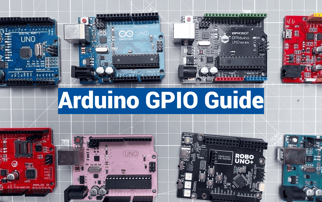
The Arduino Uno stands out as an excellent choice for beginners. This popular board features clearly labeled connection points and a robust design.
Pin headers provide sturdy connection points that are much easier to work with than the tiny pins on the microcontroller chip itself. The USB interface allows simple programming from your computer.
Your setup becomes more flexible with the DC power jack. This feature lets you power projects independently from your computer. The voltage regulators ensure stable operation across various components.
Installing the Arduino IDE and Tools
Downloading the software from the official website begins your programming adventure. The installation process follows straightforward operating system instructions.
Connect your board via USB cable to verify recognition. Navigate to the Tools menu to select your specific Arduino Uno model and communication port.
This initial setup ensures smooth communication between your computer and the microcontroller. Each pin becomes programmable once this connection establishes properly.
The development environment provides everything needed to bring your concepts to life. You’ll soon be controlling lights, sensors, and motors through the available pins.
Essential gpio arduino Concepts
Imagine being able to program a single connection point to serve multiple purposes. This flexibility is what makes working with microcontrollers so powerful and creative.
Defining GPIO and Its Functions
General-Purpose Input/Output pins are the versatile connection points on your board. Their main function is to bridge your code with physical components.
Each pin can be configured as either an input or output. As inputs, they read the state of buttons and sensors. As outputs, they send signal commands to control various devices.
This dual capability means the same physical pins can perform different tasks in different projects. Today they might read temperature data, tomorrow control motor speed.
Benefits of Using GPIO in Projects
The primary advantage is incredible adaptability. You can create interactive systems that both sense and respond to their environment.
Input pins gather information about external conditions. Output pins then act on this data by controlling lights, motors, or other components.
This approach simplifies project design significantly. You work with a standardized set of connection points rather than specialized hardware for each function.
The digital signal system uses simple HIGH/LOW states. This makes programming intuitive while providing reliable control over connected devices.
Configuring Digital I/O with Arduino Functions
Before any component can respond to your code, you must first define how each pin will behave. This configuration process uses simple but essential programming functions that establish clear communication between your microcontroller and external devices.
Understanding the Arduino pinMode() Function
The pinMode function serves as your starting point for digital I/O configuration. This crucial function tells your microcontroller whether a specific pin should act as an input or output connection point.
You call this function with just two parameters: the pin number and the desired mode. For example, pinMode(13, OUTPUT) prepares pin 13 to control external components. Always place these calls in your void setup section for proper initialization.
Effective Use of digitalWrite() for Output
Once you’ve configured a pin as OUTPUT using pinMode, the digitalWrite function takes control. This command lets you set the pin state to HIGH (5V) or LOW (0V) with simple code.
The digitalWrite function requires the pin number and desired state as parameters. For instance, digitalWrite(13, HIGH) activates an LED connected to that output pin. This function executes quickly, taking about 4 microseconds on most boards.
| Function | Purpose | Parameters | Typical Location |
|---|---|---|---|
| pinMode | Configures pin behavior | pin number, mode | void setup |
| digitalWrite | Controls output state | pin number, state | void loop |
| Execution Time | ~4 microseconds | Immediate effect | Real-time control |
Advanced Arduino GPIO Techniques
What if you could make your pin operations sixteen times faster than standard functions allow? Advanced techniques unlock this performance potential for demanding projects.
These methods go beyond basic input and output configuration. They provide precise control over timing and speed when standard approaches fall short.
Measuring DigitalWrite Speed and Performance
Testing reveals the built-in digitalwrite function takes exactly 4 microseconds. This might seem fast but limits time-critical applications.
You can measure execution speed using the micros() function. This provides accurate timestamps for performance analysis.
Arduino Port Manipulation for Fast I/O
Port manipulation bypasses standard function overhead. You write directly to the microcontroller‘s registers instead.
This advanced technique achieves pin state changes in just 0.25 microseconds. That’s approximately 16 times faster than digitalWrite.
The trade-off requires deeper knowledge of your board’s architecture. You sacrifice some safety features for maximum performance.
Utilizing Analog Pins as Digital I/O
Analog pins like A0-A5 can serve as additional digital connection points. This flexibility maximizes your board’s capabilities.
Configure them using standard pinMode commands. Then control their state with digitalRead and digitalWrite functions.
Remember that different boards have different voltage levels. ESP32 gpio pins operate at 3.3V and aren’t 5V tolerant.
| Technique | Execution Time | Skill Level | Best Use Cases |
|---|---|---|---|
| Standard digitalWrite | 4 microseconds | Beginner | General purpose projects |
| Port manipulation | 0.25 microseconds | Advanced | High-speed applications |
| Analog as digital | Same as digital pins | Intermediate | Maximizing pin usage |
Implementing Practical Projects with Arduino
The moment an LED first blinks to life under your control marks a significant milestone in any electronics journey. These hands-on examples transform abstract programming concepts into tangible, working circuits.
You’ll build confidence as you see immediate results from your code. Each project reinforces fundamental principles in a memorable way.
LED Blinking and Basic Output Examples
The classic LED blink is the “Hello World” of microcontroller projects. This simple example proves your board is working correctly.
Configure pin 13 as OUTPUT in your setup function. Then, in the void loop, alternate between HIGH and LOW states. Use the delay function to create visible blinking.
Without proper timing, the LED would blink too fast to see. The delay controls the on/off rhythm clearly.
Button Controlled LED Projects
Move beyond simple blinking to interactive circuits. A button-controlled LED demonstrates input reading combined with output control.
Connect a button to pin 4 with a pull-down resistor. Configure it as INPUT in your setup. Read the button state using digitalRead.
When the button is pressed, turn the LED on. Release it to turn the LED off. This creates immediate feedback between physical input and visual output.
| Project Type | Primary Function | Key Components | Learning Outcome |
|---|---|---|---|
| LED Blinking | Basic output control | LED, current-limiting resistor | Timing and output configuration |
| Button-Controlled LED | Input-to-output response | Button, pull-down resistor, LED | Interactive circuit design |
| Safety Consideration | Current protection | 330Ω resistor for LED | Proper circuit protection |
| Programming Pattern | Setup and loop structure | pinMode, digitalRead/Write | Code organization skills |
Always use a 330Ω current-limiting resistor with your LED. This prevents damage to both components. Never exceed 20mA per pin.
These practical examples build essential troubleshooting skills. You’ll understand how code changes affect physical behavior.
Best Practices for Voltage, Current, and Signal Integrity
Electrical safety should always be your top priority when connecting components to your development board. Proper handling of voltage levels and current limits prevents damage while ensuring reliable operation.
Ensuring Safe Voltage Levels and Current Limits
Digital pins output 5V when set to high and 0V when set to low. Never exceed these ranges on input pins. Each output pin can handle up to 40mA maximum.
This current rating works for small LEDs with proper resistor protection. However, it’s insufficient for motors or high-power devices. Always use current-limiting resistors to prevent excessive current draw.
| Resistor Type | Typical Value | Primary Purpose | Common Application |
|---|---|---|---|
| Current-Limiting | 330Ω | Protect LEDs from excess current | LED circuits |
| Pull-Up | 10kΩ | Prevent floating input pins | Button and switch circuits |
| Pull-Down | 10kΩ | Ensure LOW state when inactive | Input pin stabilization |
| Voltage Divider | Various values | Level shifting between voltages | 3.3V/5V compatibility |
Managing Signal Integrity and Noise Reduction
Floating input pins pick up electrical noise and produce unreliable readings. Use pull-up or pull-down resistors to maintain stable signal levels.
Connect a 10kΩ resistor from the input pin to either VCC (pull-up) or ground (pull-down). This ensures clean high low transitions without erratic behavior.
Mechanical buttons require debouncing techniques. Their contacts physically bounce, creating multiple rapid transitions. Software delays or hardware capacitors filter these bounces for single, clean presses.
Always verify voltage compatibility before connecting devices. Protection diodes provide some safety, but careful design prevents permanent damage to your components.
Exploring Additional Code Samples and Resources
Debugging and refining your programs becomes significantly easier when you utilize tools like the serial monitor to observe your code’s behavior in real-time. This section points you toward valuable code repositories and learning materials.
These resources help you move from basic concepts to sophisticated projects. You can see how experienced developers structure their work.
Dive into Detailed Code Examples
Well-commented code examples are incredible learning tools. They show not just what to write, but why each line matters.
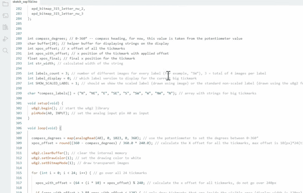
For instance, using the Serial library is simple. Adding Serial.begin(9600) in setup and Serial.println() in your loop lets you monitor variable states. This is perfect for troubleshooting.
Look for examples that demonstrate reading button states or controlling multiple outputs. Good comments explain the purpose of every section.
Supplementary Tutorials and Project Links
Online communities and forums are treasure troves of information. You can find solutions to specific problems and ask questions.
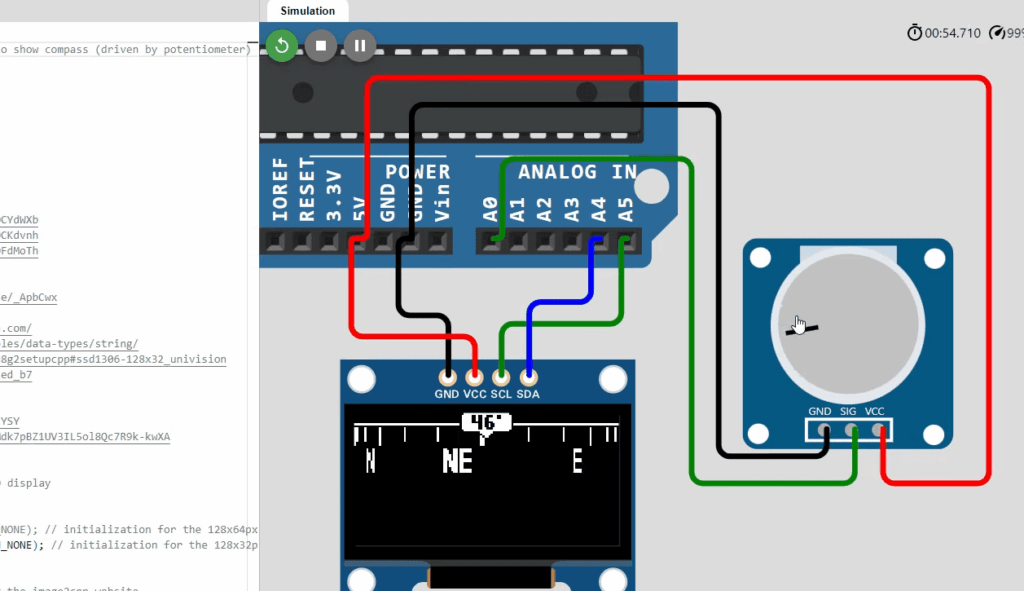
Specialized tutorials cover advanced topics like INPUT_PULLUP modes. Simulation platforms offer a risk-free way to test your code before building.
These links to official documentation and open-source projects provide pathways for continuous learning. They help you grow from a beginner to an advanced developer.
Conclusion
The knowledge you’ve gained transforms abstract programming concepts into tangible, working electronics projects. You now possess the essential skills to configure connection points, read sensor data, and control various devices with confidence.
This comprehensive tutorial has equipped you with practical techniques for both basic and advanced applications. You understand how to set pin states correctly and build safe, reliable circuits.
Your journey continues as you apply these fundamentals to more complex projects. Each new creation will deepen your understanding of microcontroller interaction with the physical world.
Keep experimenting and building—every project offers valuable learning opportunities. The skills mastered here serve as your foundation for all future electronics adventures.