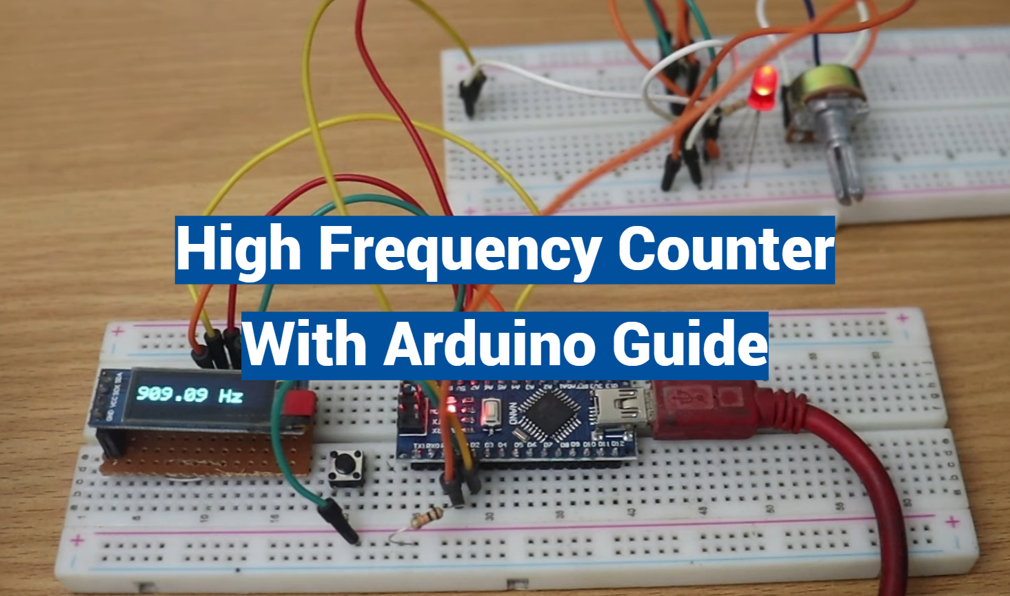
Welcome to this guide on creating a High Frequency Counter with Arduino. This powerful tool is an integral aspect of many electronics projects, and mastering its use can significantly broaden your DIY capabilities. Whether you’re a seasoned Arduino enthusiast or a beginner, this guide will provide an easy step-by-step process to successfully build a High Frequency Counter with your Arduino setup. Let’s embark on this exciting journey of exploration and learning together.
How Counters Work
Electronic counters, also known as frequency counters, use digital circuits to measure the frequency of an input signal. They work by counting the number of cycles or pulses in a given time interval and then calculating the frequency based on this count.
In this guide, we will focus on building a high frequency counter using an Arduino board. The Arduino is a popular microcontroller platform that allows for easy prototyping and programming of electronic circuits. It can be used to read input signals, perform calculations, and generate output signals.
Before we dive into building our high frequency counter, let’s first understand the basic components of a typical electronic counter.
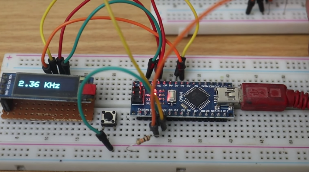
Components of an Electronic Counter
- Input: This is the signal that will be measured by the counter. In our case, this will be a high frequency signal from an external source such as a generator or oscillator.
- Clock: The clock is used to trigger the counter at regular intervals, allowing it to count the number of pulses within a specific time period.
- Counter Register: This is where the count value is stored and updated as the pulses are counted.
- Display: The display shows the final frequency measurement in a human-readable format such as Hertz (Hz).
Some electronic counters may also have additional features such as a built-in timer or the ability to display multiple units of measurement. [1]
Building a High Frequency Counter with Arduino
Now that we have a basic understanding of how counters work and their components, let’s see how we can use an Arduino board to build our own high frequency counter.
First, we will need the following materials:
- Arduino board (e.g. Uno or Nano)
- Breadboard
- Jumper wires
- LCD display (compatible with Arduino)
- High frequency signal generator or oscillator
Once we have all the necessary materials, we can start building our circuit. The steps are as follows:
- Connect the power and ground pins of the Arduino to the breadboard.
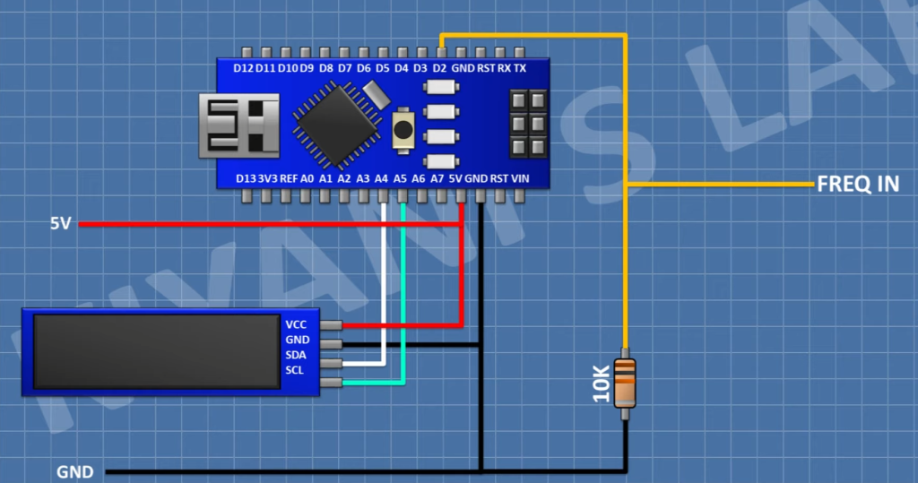
- Connect the signal generator or oscillator to one of the digital input pins of the Arduino.
- Connect the LCD display to the breadboard and connect it to the Arduino using jumper wires.
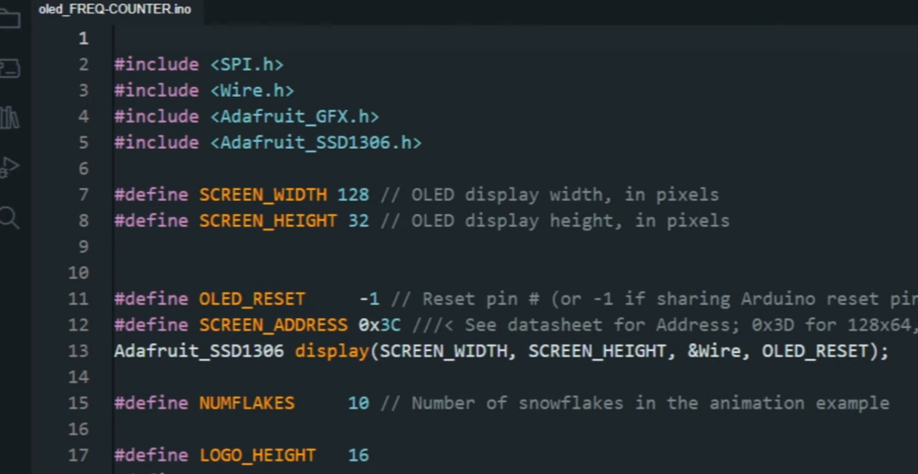
- Write a code in the Arduino software that will read the input signal, count the number of pulses within a specific time period (determined by the clock), and display the frequency on the LCD.
- Upload the code to the Arduino and test it with different input signals to ensure accurate measurements.
Congratulations, you have successfully built your own high frequency counter using an Arduino board!
Other Applications of Counters
Counters are not only limited to measuring frequencies. They can also be used in other applications such as:
- Event counting: This involves counting the number of times a specific event occurs within a given time period. For example, counting the number of cars that pass through a toll booth in an hour.
- Time interval measurement: Counters can also be used to measure time intervals by counting the number of clock cycles within a given time period.
- Position tracking: By using multiple counters and sensors, it is possible to track the position of an object in a system. This is commonly used in robotics and automation. [2]
Types of High Frequency Counters
Direct Counting Type
This type of counter directly counts the pulses from an input signal and displays the frequency on a display. It is simple and easy to use but may have limited accuracy.
Reciprocal Counting Type
Reciprocal counting involves dividing the input signal by a constant value using a frequency divider circuit, which then allows for more accurate measurements of high frequencies.
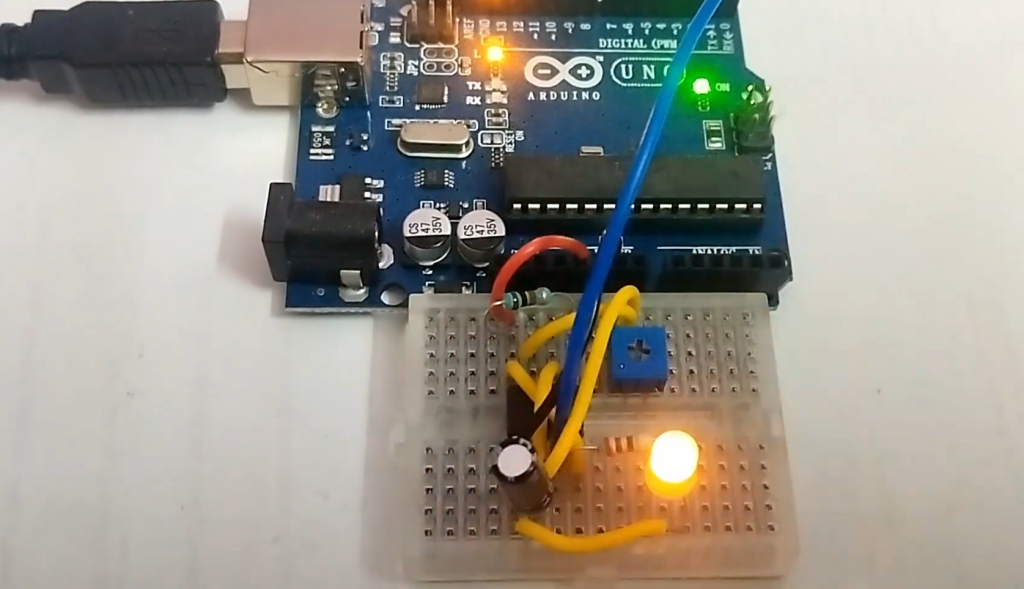
Programming the Arduino Board
To program the Arduino board, you will need to have some basic knowledge of programming in C++. The code for our high frequency counter can be found online or you can try writing your own from scratch.
Some tips for programming the Arduino:
- Use variables to store the count value and other necessary values.
- Utilize functions to organize your code and make it easier to read and modify.
- Test your code with different input signals to ensure accurate measurements.
Testing and Troubleshooting Tips
- Check all connections and ensure they are secure.
- Make sure the signal generator or oscillator is functioning properly.
- Adjust the code if necessary for different input signals.
If you encounter any issues, don’t be discouraged! Troubleshooting is a normal part of building electronic circuits and can help improve your skills as an electronics enthusiast. With persistence and perseverance, you will be able to build a working high frequency counter with your Arduino board.
Tips and Tricks for Accurate Frequency Measurement
When it comes to frequency measurement, there are a few tips and tricks that can help you achieve more accurate results. Whether you’re using an Arduino or any other high frequency counter, these techniques can help improve the accuracy of your measurements.
Use a Stable Power Source
The first tip for accurate frequency measurement is to use a stable power source. Unstable power sources can introduce noise and fluctuations in your measurements, which can affect the accuracy of your frequency readings. Make sure to use a reliable and stable power source for your counter to get more accurate results. [3]
Use Shielded Cables
Another way to reduce noise and improve accuracy is to use shielded cables. These cables are designed to reduce interference from external sources, such as electromagnetic fields or radio waves. By using shielded cables, you can minimize the impact of external factors on your frequency measurements.
Minimize Signal Reflections
Signal reflections can also affect the accuracy of your frequency measurements. These reflections occur when a signal encounters an impedance mismatch at a point in the circuit, causing it to bounce back and interfere with subsequent readings. To minimize this effect, use proper impedance matching techniques and ensure that your cables are properly terminated. [4]
Use Averaging Techniques
If you’re dealing with a noisy signal, using averaging techniques can help improve the accuracy of your frequency measurements. These techniques involve taking multiple readings and calculating an average value to reduce the impact of noise on your measurements. This is especially useful for high frequency signals where noise can be a major issue.
Consider the Sampling Rate
The sampling rate of your counter can also affect the accuracy of your frequency measurements. A higher sampling rate means that more data points are being collected, which can improve the precision of your readings. However, it’s important to note that a high sampling rate may also increase the processing time required for each measurement.
Use High-Quality Components
By following these tips and tricks, you can ensure that your frequency measurements are as accurate and precise as possible. Whether you’re working on a small hobby project or a professional application, these techniques can help you achieve more reliable results with your high frequency counter. So, keep them in mind next time you’re working on a frequency measurement project! [5]
FAQs
What is a High Frequency Counter?
A high frequency counter is an electronic device that counts the number of cycles of a periodic signal per unit time. It is typically used to measure the frequency, or number of oscillations, of a waveform in hertz (Hz).
How does a High Frequency Counter work?
A high frequency counter works by using a precision oscillator as its time base and counting the number of cycles of the input signal for a specific time period. The counter then calculates the frequency by dividing the number of cycles counted by the time period.
What are some applications of High Frequency Counters?
High Frequency Counters have a wide range of applications in various fields, such as telecommunications, radio and TV broadcasting, scientific research, and electronic testing and measurement. They are commonly used to measure the frequency of signals in electronic circuits, as well as in laboratory experiments and industrial settings.
Can I build a High Frequency Counter using an Arduino?
Yes, it is possible to build a high frequency counter using an Arduino. The Arduino platform provides a versatile and affordable option for building DIY electronics projects, including high frequency counters. With the right components and programming, an Arduino can be used as a reliable and accurate high frequency counter.
What components do I need to build a High Frequency Counter with an Arduino?
To build a high frequency counter with an Arduino, you will need the following components:
- An Arduino board (such as Uno or Mega)
- A precision oscillator module (such as TCXO or OCXO)
as the time base
- A frequency divider IC (such as CD4040) to extend the counting range
- A display module (such as a 7-segment LED display) to show the frequency output
- Connecting wires and a breadboard for prototyping
Are there any pre-made High Frequency Counter modules available for Arduino?
Yes, there are pre-made high frequency counter modules available for Arduino. These modules come with all the necessary components and are ready to use with minimal wiring and programming. They can be easily found online from electronics suppliers or hobbyist stores.
Are there any limitations of building a High Frequency Counter with an Arduino?
While building a high frequency counter with an Arduino is possible, it does have some limitations. The Arduino’s internal clock has a limited frequency range and may not be accurate enough for high precision measurements. Additionally, the accuracy of the counter may also be affected by external factors such as noise and interference.
Can I use a High Frequency Counter for measuring other parameters besides frequency?
Yes, some high frequency counters can also measure other parameters such as period (time between cycles), duty cycle, and pulse width. These additional features can be useful for more advanced electronic testing and measurement applications.
Are there any resources or tutorials available for building a High Frequency Counter with an Arduino?
Yes, there are many online resources and tutorials available for building a high frequency counter with an Arduino. These include step-by-step guides, circuit diagrams, and code examples to help you get started. Additionally, there are online communities and forums where you can ask questions and receive support from fellow DIY electronics enthusiasts. So if you’re interested in building your own high frequency counter with an Arduino, there’s no shortage of helpful resources available to guide you through the process.
How does Arduino interface with a High Frequency Counter?
Arduino can interface with a high frequency counter through its digital input/output (I/O) pins. The precision oscillator and frequency divider are connected to the Arduino’s I/O pins, allowing it to count the cycles of the input signal and display the frequency output on a display module. Additionally, Arduino can also be programmed with various functions and calculations to enhance the capabilities of the high frequency counter.
Are there any other alternatives to using an Arduino for building a High Frequency Counter?
Yes, there are other alternatives to using an Arduino for building a high frequency counter. Some examples include using dedicated high frequency counter chips or microcontrollers, as well as purchasing pre-made high frequency counter devices. These alternatives may offer more advanced features and higher accuracy, but they also come at a higher cost.
Can I modify or customize my High Frequency Counter built with Arduino?
Absolutely! One of the great things about building your own high frequency counter with an Arduino is the ability to modify and customize it according to your specific needs and preferences. You can experiment with different components, add new features and functions through coding, and even create a unique design for your counter’s display. The possibilities are endless when it comes to customizing your own high frequency counter with an Arduino.
Does the Arduino board support all frequency ranges for High Frequency Counters?
The Arduino board has a limited frequency range for its internal clock, typically up to 16MHz. However, by using external precision oscillators and frequency dividers, it is possible to extend the frequency range of the high frequency counter built with an Arduino. This allows for a wider range of application possibilities and more accurate measurements.
What steps should I follow to calibrate my High Frequency Counter with Arduino?
Calibrating a high frequency counter built with Arduino involves adjusting the precision oscillator to ensure accurate frequency measurements. The following steps can serve as a general guide for calibration:
- Connect the input signal to be measured to the Arduino’s digital I/O pin.
- Use the appropriate code and functions to count the number of cycles in a specific time period and display the frequency output.
- Compare the measured frequency to a known reference frequency (i.e. from another calibrated device) and note any differences.
- Adjust the precision oscillator’s trimmer capacitor or potentiometer to fine-tune the frequency until it matches the reference frequency.
- Repeat steps 2-4 as needed until the desired accuracy is achieved.
It is important to note that calibration methods may vary depending on the specific components and circuit used in the high frequency counter. It is recommended to consult online resources or seek guidance from experienced individuals if needed.
What are the common troubleshooting steps if my High Frequency Counter isn’t working with Arduino?
If your high frequency counter built with Arduino is not working properly, there are a few common troubleshooting steps you can take:
- Check all connections and wiring to ensure they are secure and in the correct position.
- Ensure that the input signal is within the frequency range of the Arduino’s internal clock (or external precision oscillator, if used).
- Check for any loose or damaged components and replace them if necessary.
- Verify that the code used is correct and matches the circuit diagram.
- Use a known reference frequency to test the accuracy of the counter’s measurements.
If these steps do not resolve the issue, it may be helpful to consult with online resources or seek assistance from experienced individuals in troubleshooting electronic circuits. In some cases, it may be necessary to replace certain components or modify the circuit design for optimal functionality.
Conclusion
Building a high frequency counter with an Arduino is not only a fun and educational DIY project, but it also offers practical applications for electronics testing and measurement. With the wide range of available resources and the ability to modify and customize your own counter, there’s no limit to what you can achieve with this versatile device. So if you’re interested in expanding your electronic skills and capabilities, give building a high frequency counter with an Arduino a try! Keep learning and experimenting to enhance your knowledge and creativity in the world of electronics. Happy tinkering!
Useful Video: Pulse Frequency Counter using Arduino
References:
- https://forum.arduino.cc/t/high-frequency-counter/319854
- https://circuitdigest.com/microcontroller-projects/arduino-frequency-counter-circuit
- http://www.wa5bdu.com/an-arduino-frequency-counter/
- https://www.circuitstoday.com/frequency-counter-using-arduino
- https://www.changpuak.ch/electronics/Arduino-24_GHz_Counter.php

