Dive into the world of Controller Area Network (CAN) Bus systems with our detailed guide on building a CAN Bus using an Arduino. This article will walk you through the process, from setting up the hardware to installing the necessary libraries and uploading your first code.
We’ll delve into the message-based protocol of the CAN Bus, explaining how it enables centralized control over electronic devices connected to the network. Whether you are using an Arduino UNO R4 Minima or interfacing with the MCP2515 CAN Bus Module, this guide will provide insight into the intricacies of CAN Bus communication.
What Is CAN-BUS?
It was initially developed by Bosch in the 1980s to facilitate communication between various electronic control units (ECUs) in automobiles [2]. Since then, it has become the de facto standard for in-vehicle communication systems.
How Does CAN-BUS Work?
The core principle behind CAN-BUS is a multi-master, message-based protocol. Unlike traditional serial communication protocols like UART (Universal Asynchronous Receiver-Transmitter), SPI (Serial Peripheral Interface), and I2C (Inter-Integrated Circuit), CAN-BUS operates as a broadcast network. This means that multiple devices can simultaneously transmit and receive data on the same bus without the need for a centralized controller.
Why Use the CAN Protocol Rather Than UART, SPI, and I2C:
1. Low Cost
One of the most significant advantages of CAN-BUS is its cost-effectiveness. The hardware requirements for CAN-BUS are minimal, with only a few inexpensive components needed to set up a network. This makes it an attractive choice for mass-produced vehicles and other applications where cost is a critical factor [3].
2. Centralized
Unlike UART, SPI, and I2C, CAN-BUS offers a centralized communication model. Instead of relying on a single master device to coordinate communication, CAN-BUS allows all devices on the network to communicate directly with each other. This distributed approach simplifies system design and increases fault tolerance.
3. Flexible
CAN-BUS is highly flexible and can be adapted to various communication requirements. It supports different data rates, message priorities, and message lengths, making it suitable for a wide range of applications beyond automotive systems.
4. Robust
Automotive environments are harsh, with significant electrical noise and potential interference. CAN-BUS is designed to be robust in such conditions. It uses differential signaling, error detection, and fault tolerance mechanisms to ensure reliable communication even in noisy environments.
5. Efficient
CAN-BUS is an efficient protocol in terms of both bandwidth utilization and power consumption. It minimizes data collisions and allows for efficient data sharing among connected devices. This efficiency is essential for real-time systems like those found in modern vehicles.
The Role Of CAN
CAN-BUS plays a pivotal role in modern automobiles. It connects various electronic control units (ECUs) that manage critical vehicle functions. These ECUs include the engine control module (ECM), transmission control module (TCM), anti-lock braking system (ABS), airbag control module, and many others [4].
CAN-BUS enables these modules to exchange information rapidly, ensuring precise coordination of vehicle systems for optimal performance, safety, and efficiency.
CAN-BUS Wiring Sequence
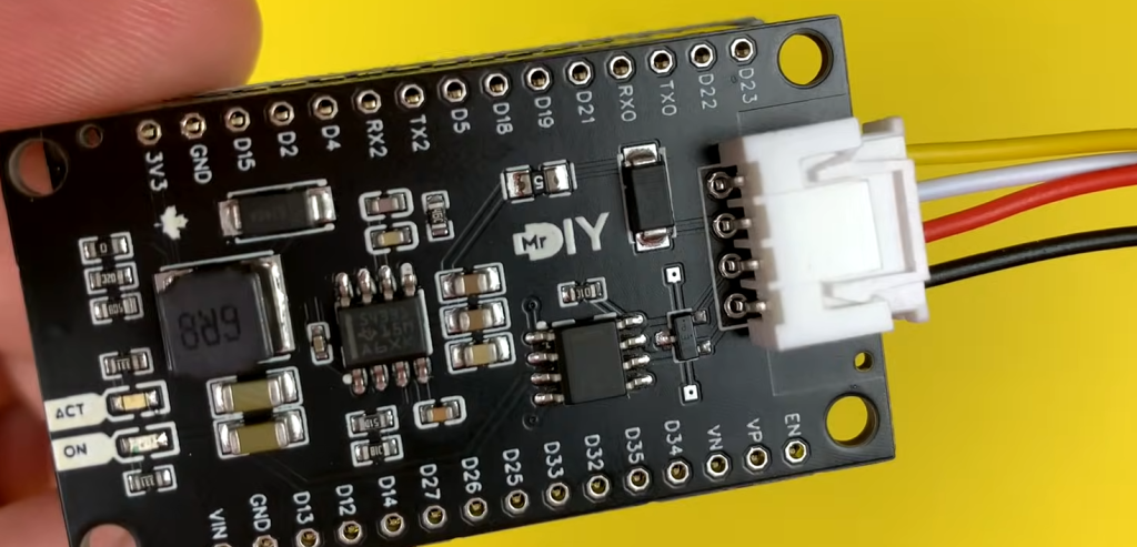
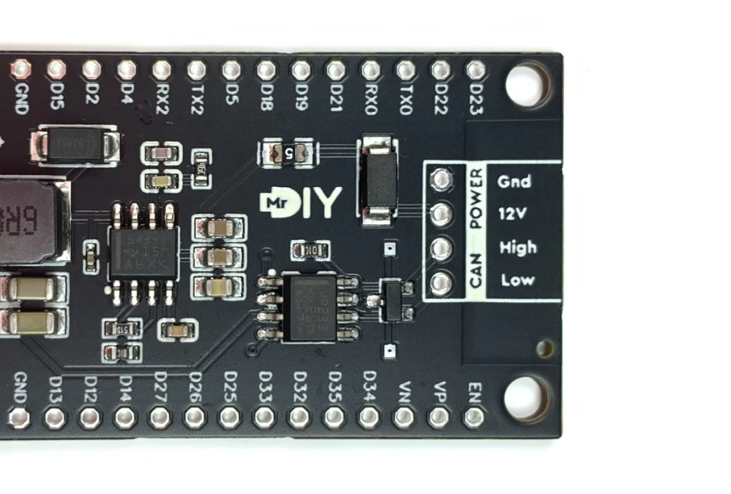
For CAN-BUS to function correctly, proper wiring is crucial. A standardized wiring sequence ensures that all devices on the network can communicate effectively. The wiring consists of two lines: CAN-High (CAN-H) and CAN-Low (CAN-L) [5].
These lines are twisted together to reduce electromagnetic interference (EMI) and improve signal integrity. To ensure compatibility, it’s essential to use the correct wiring sequence and connectors when setting up a CAN-BUS network.
CAN Protocol Speed and Range
The speed and range of a CAN-BUS network can vary depending on the specific application and requirements. CAN-BUS typically operates at speeds ranging from 125 Kbps to 1 Mbps. The choice of speed depends on the data transfer needs of the connected devices.
In terms of range, CAN-BUS is designed for short-distance communication within a vehicle, typically up to 40 meters (about 131 feet). However, repeaters and other techniques can be used to extend the range for specific applications.
CAN Message
In a CAN-BUS network, communication occurs through messages. Each message consists of an identifier and data. The identifier, often referred to as the message ID, specifies the type and priority of the message. Data can range from a single byte to eight bytes, allowing for the transmission of a wide range of information. Messages are broadcast to all devices on the network, and each device determines whether the message is relevant based on its unique identifier.
CAN-BUS vs OBD2
OBD2, or On-Board Diagnostics 2, is a standardized system used in modern vehicles to monitor and report on the health and performance of various vehicle systems. While OBD2 and CAN-BUS are closely related, they serve different purposes.
OBD2:
OBD2 is primarily a diagnostic system. It provides a standardized interface for connecting diagnostic tools to a vehicle’s onboard computer systems. The data available through OBD2 includes information about engine performance, emissions, and other parameters. OBD2 is mandated by law in many regions to ensure emissions compliance and facilitate vehicle diagnostics.
CAN-BUS:
CAN-BUS, on the other hand, is the communication protocol that enables different ECUs within the vehicle to exchange data. While OBD2 uses the CAN-BUS protocol for some of its communication, CAN-BUS is not limited to diagnostics [6]. It also handles essential vehicle functions, such as engine control and transmission management. In essence, CAN-BUS is the backbone of modern vehicle communication, while OBD2 is an application that runs on top of it.
How to Build a CAN Bus With a Breadboard and Arduino:
1. Initializing the CAN Bus
Components You’ll Need:
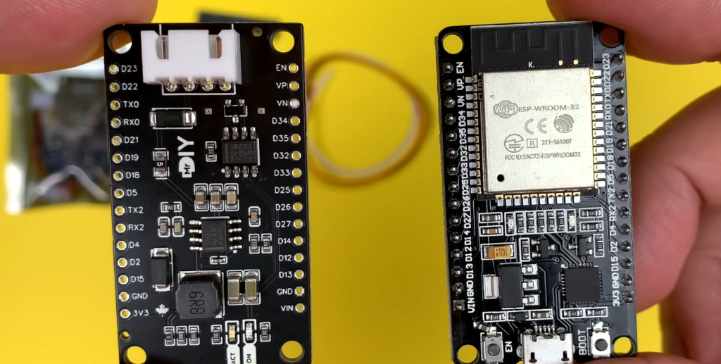
- Arduino (e.g., Arduino Uno);
- MCP2515 CAN controller module;
- Breadboard and jumper wires;
2. Steps:
Wiring Connections
Start by connecting your Arduino and MCP2515 module to the breadboard. Connect the following pins:
- Arduino 5V to MCP2515 VCC;
- Arduino GND to MCP2515 GND;
- Arduino SPI MOSI (Master Out Slave In) to MCP2515 SI (Serial Input);
- Arduino SPI MISO (Master In Slave Out) to MCP2515 SO (Serial Output);
- Arduino SPI SCK (Serial Clock) to MCP2515 SCK (Serial Clock);
- Arduino digital pin (e.g., D2) to MCP2515 CS (Chip Select) [7];
Install CAN Library:
To work with CAN-BUS on Arduino, you’ll need a CAN library. You can use the “MCP_CAN” library, which provides functions for CAN communication with the MCP2515 module. Install this library via the Arduino IDE’s Library Manager.
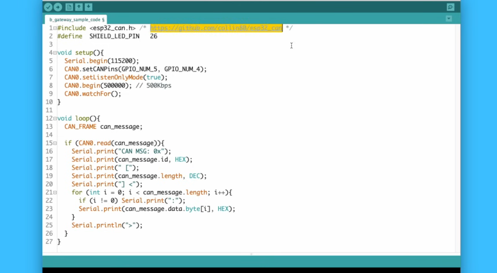
Code Initialization
Write a simple Arduino sketch to initialize the CAN bus. Here’s an example code snippet:
#include
#include
const int spiCS = 2; // Chip Select pin
MCP_CAN CAN(spiCS); // Initialize MCP2515
void setup() {
Serial.begin(9600);
while (!CAN.begin(CAN_125KBPS)) {
Serial.println(“CAN BUS Shield init fail”);
delay(100);
}
Serial.println(“CAN BUS Shield init OK!”);
}
void loop() {
// The code goes here
}
This code initializes the MCP2515 module and sets the CAN bus speed to 125 kbps.
3. MCP2515 CAN Operational Modes
The MCP2515 module supports various operational modes, including Normal, Sleep, Loopback, Listen-Only, and Configuration. These modes allow you to configure the behavior of the CAN controller for different tasks. For example, the Loopback mode allows you to test sending and receiving data within your Arduino without involving external devices, while the Listen-Only mode lets you monitor the bus without transmitting.
To set the operational mode, use the CAN.setMode(MODE) function in your Arduino code, where MODE is one of the mode constants (e.g., CAN_NORMAL_MODE, CAN_SLEEP_MODE, CAN_LOOPBACK_MODE, etc.).
4. Sending Data Over the CAN Bus
Sending data over the CAN bus involves creating a CAN message, setting its identifier and data, and then transmitting it.
Here’s a simplified example:
void sendCANMessage() {
tCAN message;
message.id = 0x123; // Set the message ID
message.header.rtr = 0; // Data frame (not a remote transmission request)
message.header.length = 8; // Data length (in bytes)
message.data[0] = 0x01; // Data byte 1
message.data[1] = 0x02; // Data byte 2
// Add more data bytes as needed
CAN.sendMsgBuf(message.id, 0, message.header.length, message.data);
}
This function creates a CAN message with a specific ID and data and then sends it using the CAN.sendMsgBuf function [8].
5. Receiving Data From the CAN Bus
Receiving data from the CAN bus involves checking for incoming messages and processing them.
Here’s an example of receiving and printing messages:
void receiveCANMessage() {
tCAN message;
if (CAN.checkReceive()) {
CAN.readMsgBuf(&message.id, &message.header.length, message.data);
Serial.print(“Received Message ID: 0x”);
Serial.print(message.id, HEX);
Serial.print(” Data: “);
for (int i = 0; i < message.header.length; i++) {
Serial.print(message.data[i], HEX);
Serial.print(” “);
}
Serial.println();
}
}
This function checks if there’s a message in the receive buffer and, if so, reads it and prints the ID and data.
With these steps, you can build a simple CAN bus system using an Arduino and the MCP2515 module. Keep in mind that this is a basic introduction to CAN communication, and real-world applications may require more advanced configurations and error handling. Experimenting with CAN communication on an Arduino provides a great starting point for learning about this essential protocol and its applications in various industries.
How to Connect a CAN Bus Transceiver to a Breadboard:
Components You’ll Need:
- Arduino (e.g., Arduino Uno);
- MCP2515 CAN controller module;
- CAN bus transceiver (e.g., MCP2551 or TJA1050);
- Breadboard and jumper wires;
- HC-SR04 ultrasonic sensor (for demonstration purposes) [9];
Steps:
1) Connect the CAN Bus Transceiver:
Start by placing your CAN bus transceiver on the breadboard. Connect it as follows:
- CANH (CAN High): Connect to the HI (high) side of the CAN bus;
- CANL (CAN Low): Connect to the LO (low) side of the CAN bus;
- VCC: Connect to 5V on your Arduino or an external 5V power source;
- GND: Connect to GND on your Arduino or the common ground with other components
- RS (Slope-Control Input): Leave unconnected or connect to GND for high-speed operation (usually not needed for standard Arduino-based projects);
2) Connect the MCP2515 Module
If you haven’t already, connect your MCP2515 CAN controller module as described in the previous section.
3) Connect Additional Components (HC-SR04 for Demonstration):
If you’re using an HC-SR04 sensor, connect it to your Arduino to demonstrate the CAN communication.
Connect the sensor as you normally would:
- VCC: Connect to 5V on your Arduino;
- GND: Connect to GND on your Arduino;
- Trig (Trigger): Connect to a digital output pin on your Arduino (e.g., D2);
- Echo: Connect to a digital input pin on your Arduino (e.g., D3);
4) Power Supply for Breadboard:
5) Verify Wiring:
Double-check your connections to ensure everything is properly wired.
Programming the MCP2515 CAN Bus Module:
- Install the MCP_CAN Library: If you haven’t already, install the “MCP_CAN” library via the Arduino IDE’s Library Manager;
- Write Your Arduino Sketch: Write your Arduino sketch, which includes initializing the CAN bus, sending data, and receiving data. Your sketch may include code for the HC-SR04 sensor or other components you’re using in your project;
- Compile and Upload: Compile your sketch and upload it to your Arduino board;
- Monitor Serial Output: If your project includes serial communication for debugging or displaying information, open the Arduino Serial Monitor to view the output;
- Test and Debug: Test your setup by sending and receiving CAN messages. Ensure that the CAN transceiver and MCP2515 module are functioning correctly. If you encounter issues, review your connections and code for any errors [10];
FAQ:
1. Does Arduino have a CAN bus?
Arduino does not natively support CAN bus communication. However, you can use external CAN controller modules like the MCP2515 and compatible libraries to add CAN bus capabilities to an Arduino.
2. How to connect Arduino to the CAN bus?
To connect an Arduino to a CAN bus, you’ll typically need an external CAN controller module (e.g., MCP2515), a CAN transceiver (e.g., MCP2551), and appropriate wiring. Connect the CAN transceiver to the CAN high (CANH) and CAN low (CANL) lines of the CAN bus [11].
Connect the CAN controller module to your Arduino via SPI (Serial Peripheral Interface) pins. Refer to the specific module’s datasheet and library documentation for detailed pin connections and code examples.
3. What is the speed of the CAN bus in Arduino?
The CAN bus speed in an Arduino project depends on your configuration and the capabilities of the CAN controller module you’re using. Common speeds for Arduino-based CAN bus projects include 125 kbps, 250 kbps, and 500 kbps. You can set the speed in your Arduino code using the appropriate library functions.
4. What is the difference between RS485 and CAN bus?
RS485 and CAN bus are both serial communication protocols, but they have distinct differences:
- RS485 is a half-duplex or full-duplex communication standard that uses differential signaling. It is often used for point-to-point or multi-point communication in industrial applications and building automation;
- CAN bus is a multi-master, message-based protocol designed for distributed communication in applications like automotive and industrial automation. It uses a differential pair for robust communication and supports multiple nodes on a single bus [12];
5. What voltage is the CAN bus?
CAN bus typically operates at 5 volts (V) for the logic levels. However, it can also be found in 3.3V variants, especially in newer automotive systems and industrial applications.
6. What is the maximum CAN bus load?
The maximum allowable load on a CAN bus depends on factors like the bus speed, cable length, and the number of connected nodes. Generally, for a standard CAN bus (ISO 11898-2), the maximum total load (resistance) of the bus should not exceed 60-120 Ohms [13], depending on the bus speed. Exceeding this limit can result in signal degradation and communication issues.
7. How many volts is a CAN bus system?
A CAN bus system operates at voltage levels of 0V (low) and 5V (high) for the dominant and recessive states, respectively, in a standard 5V logic level implementation. In some cases, 3.3V logic levels are used, particularly in newer applications.
8. Does the CAN bus use I2C?
No, the CAN bus does not use I2C (Inter-Integrated Circuit) for communication. They are two different communication protocols with distinct characteristics. CAN bus is a message-based protocol designed for robust communication in noisy environments, while I2C is a two-wire, synchronous serial protocol commonly used for communication between integrated circuits.
9. How is a CAN bus powered?
A CAN bus system is typically powered by an external power supply, often 12V or 24V in automotive and industrial applications. The power supply provides voltage to the CAN transceivers and other connected devices on the bus. The CAN controller module itself may be powered from the Arduino or an external power source, depending on the design.
10. How is the CAN bus wired?
CAN bus is wired using a twisted-pair cable, where one wire carries the CAN high (CANH) signal, and the other carries the CAN low (CANL) signal. The twisted-pair configuration helps reduce electromagnetic interference (EMI) and ensures reliable communication. Termination resistors are typically placed at each end of the bus to match the characteristic impedance of the cable and prevent signal reflections.
11. Is Ethernet a CAN bus?
Ethernet and CAN bus are different communication technologies. Ethernet is a high-speed networking standard commonly used for data transmission in computer networks, while CAN bus is a lower-speed, distributed communication protocol used in various applications, including automotive and industrial systems.
12. Is a CAN bus wireless?
CAN bus is traditionally a wired communication protocol, but there are wireless CAN bridge devices available that can transmit CAN messages wirelessly. These devices enable wireless communication between nodes on a CAN bus network.
13. Is the CAN bus wired or wireless?
The CAN bus is primarily a wired communication protocol. It uses twisted-pair cables for reliable communication in various applications. However, as mentioned earlier, there are wireless CAN bridge solutions that can be used to extend CAN communication wirelessly.
14. How many Ohms is a CAN bus system?
The characteristic impedance of a CAN bus system is typically 120 Ohms. Termination resistors of 120 Ohms are commonly used at each end of the bus to match the impedance of the cable and minimize signal reflections.
15. What is the difference between ECU and CAN bus:
- ECU (Electronic Control Unit): An ECU is a control unit or computer within a vehicle or industrial system responsible for managing specific functions or subsystems. ECUs use the CAN bus to communicate with other ECUs and sensors, sharing data and control commands to regulate various vehicle or system functions;
- CAN bus: The CAN bus is a communication protocol and physical network used to connect multiple ECUs and sensors within a vehicle or system. It serves as the communication backbone that allows ECUs to exchange data and coordinate their operations. In essence, the CAN bus enables ECUs to work together seamlessly;
Useful Video: Arduino CAN Bus Tutorial | Interfacing MCP2515 CAN Module with Arduino
References:
- https://www.makeuseof.com/how-to-connect-canbus-transceiver-to-breadboard-arduino/
- https://www.seeedstudio.com/blog/2019/11/27/introduction-to-can-bus-and-how-to-use-it-with-arduino/
- https://www.tutorialspoint.com/can-bus-with-arduino
- https://www.engineersgarage.com/getting-started-with-can-interface-with-arduino/
- https://circuitdigest.com/microcontroller-projects/arduino-can-tutorial-interfacing-mcp2515-can-bus-module-with-arduino
- https://www.hackster.io/maurizfa-13216008-arthur-jogy-13216037-agha-maretha-13216095/can-bus-using-arduino-9ce7ba
- https://www.instructables.com/Yes-We-CAN-BUS-With-Arduino-in-30-Seconds
- https://www.seeedstudio.com/blog/2019/11/27/introduction-to-can-bus-and-how-to-use-it-with-arduino
- https://www.makeuseof.com/how-to-connect-canbus-transceiver-to-breadboard-arduino
- https://docs.arduino.cc/tutorials/uno-r4-minima/can
- https://www.tutorialspoint.com/can-bus-with-arduino
- https://how2electronics.com/interfacing-mcp2515-can-bus-module-with-arduino
- https://docs.arduino.cc/software/plc-ide/tutorials/can-setup