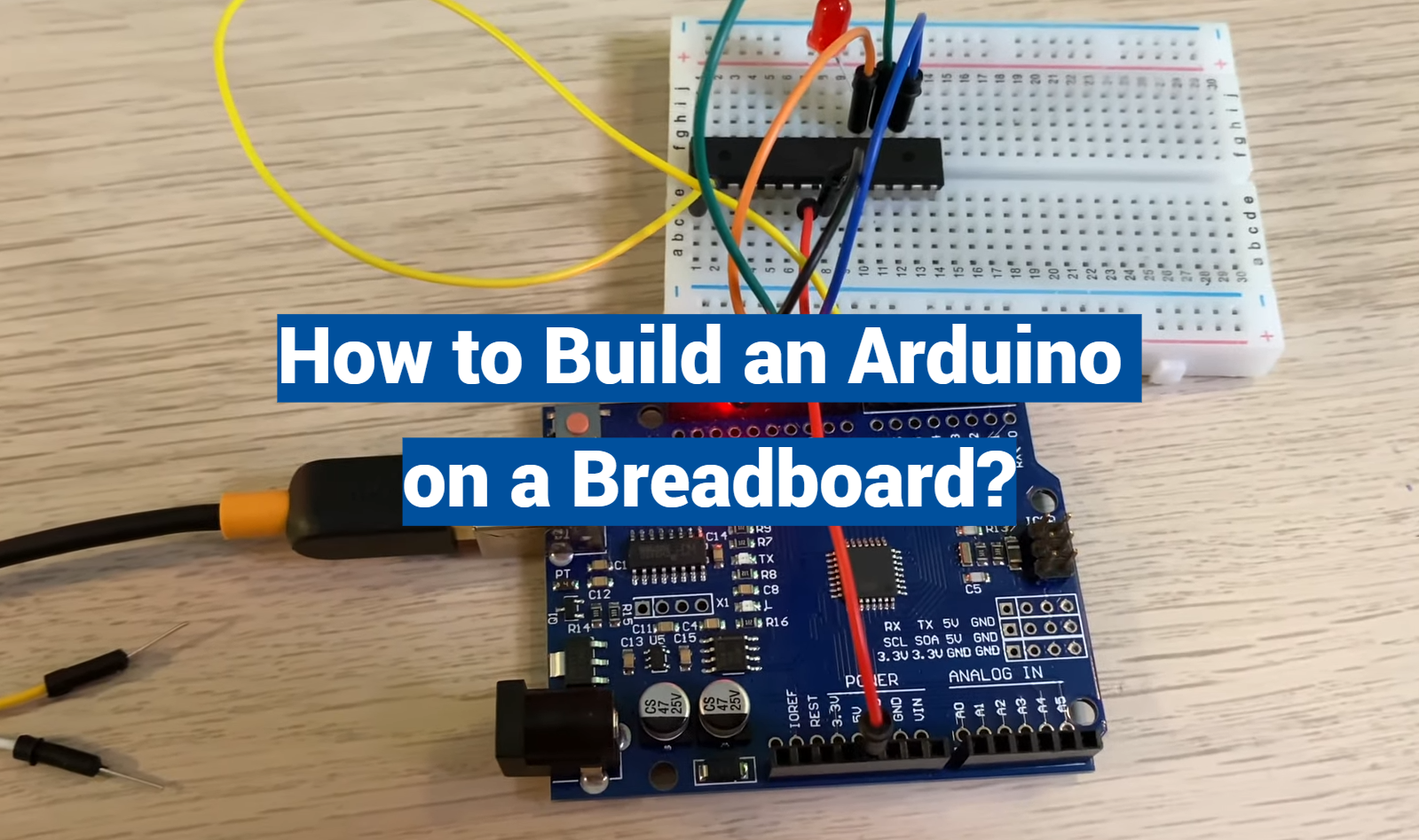
Embarking on the journey of building an Arduino on a breadboard can be an exciting and rewarding experience. This process allows you to understand the inner workings of this popular microcontroller platform and provides a versatile foundation for countless electronics projects.
Whether you’re a seasoned maker or a beginner eager to delve into the world of Arduino, this comprehensive guide will walk you through each step of the process, from setting up your breadboard to uploading your first program. With careful instructions, helpful diagrams, and expert tips, you’ll be well-equipped to bring your Arduino breadboard project to life.
History of Breadboard
The term “breadboard” may seem an unusual choice for a device used in electronics, but its origin is quite literal. In the early 20th century, when electronics was in its infancy, experimenters needed a convenient way to construct and test circuits without the need for complex and permanent wiring [1].
To achieve this, they often used wooden boards, resembling cutting boards used in kitchens, as their work surfaces. These boards had holes drilled into them to accommodate components, wires, and connectors.
The breakthrough in breadboard design came with the invention of solderless breadboards. In the 1970s, engineers and hobbyists were searching for a way to simplify circuit prototyping further. The solution was a plastic base with a grid of holes, each connected to a metal strip beneath the surface. These metal strips acted as electrical connections, eliminating the need for soldering.
The most famous solderless breadboard design is the one introduced by Electronic Design News in 1971 [2]. It featured a rectangular grid of holes, with rows and columns clearly labeled. This design made it easy to insert components and create circuits, as users could follow a standardized layout.
Types of Breadboards
1. Traditional Breadboard
The traditional breadboard, often referred to as a prototyping board, is the type most people are familiar with. It consists of a plastic base with rows and columns of interconnected holes. These interconnected holes allow users to create circuits by simply plugging in components and connecting wires. Traditional breadboards come in various sizes, but they all adhere to the same basic design principles.
2. Grove Expansion Board
The Grove Expansion Board is a specialized breadboard designed for use with Seeed Studio’s Grove System. The Grove System is a modular electronics platform that simplifies connecting sensors and actuators to microcontrollers.
The Grove Expansion Board features a grid of holes similar to a traditional breadboard but with connectors specifically designed to interface with Grove System modules. This makes it incredibly convenient for quickly prototyping projects that involve sensors, displays, and other Grove modules.
3. Base Shield V2.0 for Arduino
Arduino enthusiasts will appreciate the Base Shield V2.0, which is designed to simplify the process of connecting various sensors and modules to an Arduino board. This shield, which resembles a breadboard, comes pre-wired with common input and output interfaces.
Users can attach it directly to their Arduino board, allowing them to connect sensors, displays, and other components without the hassle of manually wiring everything. It streamlines the prototyping process, especially for those new to Arduino [3].
4. Base Hat for Raspberry Pi Zero
For Raspberry Pi Zero users, the Base Hat provides a convenient way to prototype and expand their projects. The Base Hat is a small board that fits directly on top of the Raspberry Pi Zero, offering a grid of holes for attaching components and creating circuits. It’s particularly useful when working on projects that require sensors, buttons, LEDs, or other electronic elements, as it keeps everything neatly organized and connected to the Raspberry Pi.
5. Mega Shield V1.2 for Arduino and Google ADK
The Mega Shield V1.2 is a specialized breadboard designed for use with Arduino Mega boards and the Google ADK (Android Open Accessory Development Kit). It provides an organized layout for connecting various sensors, displays, and input devices to Arduino Mega boards, making it a valuable tool for developers working on projects that require a wide range of sensors and peripherals.
6. Base Hat for Raspberry Pi
Similar to the Base Hat for Raspberry Pi Zero, the Base Hat for the standard Raspberry Pi offers a convenient way to prototype and expand Raspberry Pi projects. It sits on top of the Raspberry Pi board and provides a grid of holes for attaching components and creating circuits. Whether you’re working on a home automation project, robotics, or IoT applications, this breadboard simplifies the process of connecting sensors and other electronic elements to your Raspberry Pi.
7. Shield for Seeed Studio XIAO
The Shield for Seeed Studio XIAO is designed to work with the Seeed Studio XIAO, a compact and powerful microcontroller board. This shield expands the XIAO’s capabilities by providing a breadboard-style platform for connecting various sensors and components. It’s an excellent choice for projects that require a small form factor while still needing the flexibility of a breadboard.
How Does a Breadboard Work?
Understanding how a breadboard works is crucial for anyone involved in electronics prototyping. At its core, a breadboard provides a platform for creating temporary electrical connections between components without the need for soldering.
Here’s how it works:
1) Grid of Holes
A typical breadboard consists of a plastic base with a grid of holes arranged in rows and columns. These holes are interconnected in a specific pattern, with each row typically connected horizontally and each column connected vertically [4].
2) Component Insertion
To create a circuit on a breadboard, you start by inserting electronic components into the holes. Components like resistors, LEDs, capacitors, and integrated circuits (ICs) have wire leads or pins that can fit snugly into the breadboard’s holes.
3) Connection Strips
Beneath the surface of the breadboard, there are conductive metal strips that connect multiple holes. These strips are responsible for establishing electrical connections between components. Each row typically consists of five connected holes, while columns run the entire length of the breadboard.
4) Wiring Components
To create a circuit, you use jumper wires or leads from components to make connections between the appropriate holes. For example, you might connect the positive lead of an LED to a resistor and then connect the other end of the resistor to a hole in a different row to complete the circuit.
5) Power and Ground Rails
Most breadboards have power and ground rails running alongside the main grid. These rails are typically used to distribute voltage (VCC) and ground (GND) to various parts of the circuit. You can connect these rails to your power source or microcontroller to provide power to your components.
6) Breadboard Layout
The breadboard’s layout follows a standardized pattern, with rows and columns labeled for easy reference. This labeling helps ensure that you make the right connections and avoid mistakes when building your circuits.
7) Temporary Connections
One of the key advantages of breadboards is that the connections are temporary. If you make a mistake or want to change your circuit, you can easily remove components or wires and reconfigure the layout. This flexibility makes breadboards an excellent tool for prototyping and experimentation.
8) Testing and Debugging
Once your circuit is assembled on the breadboard, you can power it up and test its functionality. If you encounter issues or need to make modifications, you can do so quickly without any soldering. This ability to iterate and refine your circuits is invaluable during the design and prototyping phases of electronics projects.
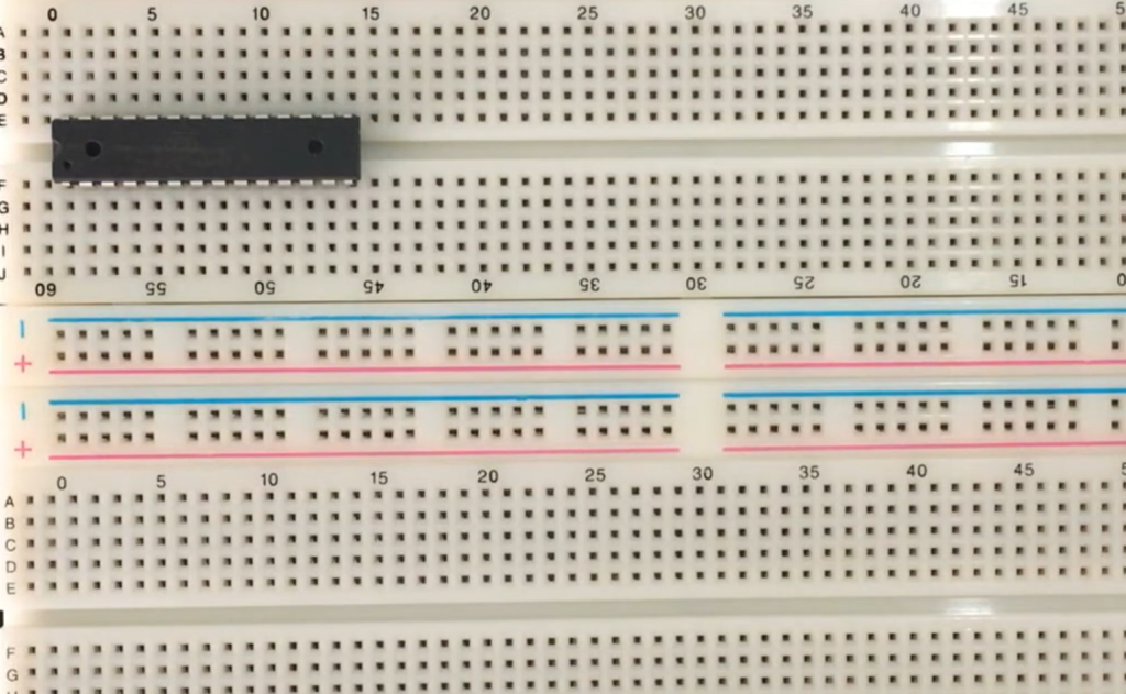
9) Center Groove (DIP Support)
Many breadboards feature a center groove or DIP support area. This area is designed to accommodate integrated circuits (ICs) with dual inline packages (DIPs). DIPs are common IC packages with two rows of pins that can be easily plugged into the breadboard. The center groove provides a secure and stable platform for placing ICs, allowing you to connect them to the rest of your circuit easily.
10) Other Features of a Breadboard
While the basic construction and components of a breadboard are relatively consistent, some breadboards come with additional features and design elements:
- Self-Adhesive Backing: Some breadboards have a self-adhesive backing that allows you to attach them to a project enclosure or other surfaces, providing stability during prototyping;
- Binding Posts: High-quality breadboards may include binding posts for securely connecting power sources, making it easier to supply voltage to your circuit;
- Multiple Bus Strips: Advanced breadboards may feature multiple sets of bus strips for distributing different voltage levels, such as +5V, +3.3V, and GND;
- Breadboard Labels: Some breadboards come with printed labels or markings to help identify rows, columns, and the location of bus strips;
How Is A Breadboard Constructed:
Bus and Terminal Strips
1. Bus Strips
Bus strips, also known as power rails, are long strips that run parallel to each other on both sides of the breadboard. They are typically labeled as “+” (positive or VCC) and “-“ (negative or GND) [5]. These strips are used to distribute power and ground throughout the breadboard. Connecting components to these bus strips ensures they have access to the necessary voltage and ground connections.
2. Terminal Strips
The terminal strips, which make up the majority of the breadboard’s surface, are composed of rows and columns of interconnected holes. Each row typically contains five interconnected holes, while each column runs vertically through the breadboard. Components and wires are inserted into these holes to create electrical connections.
Metal Clips
Beneath the surface of a breadboard are metal clips that facilitate electrical connections. These clips are responsible for connecting holes in the terminal strips, allowing for the flow of electrical current. When you insert a component or a wire into a hole, the metal clip beneath it makes contact with the component’s lead or wire, creating an electrical connection.
The ingenious design of these metal clips ensures that connections are temporary and can be easily modified or removed, making breadboards an ideal platform for prototyping and experimentation.
How to Read Breadboard Rows and Columns?
Rows
Rows on a breadboard are typically labeled with numbers, starting from 1 and increasing as you move down the board. Each row contains five interconnected holes. It’s essential to recognize that all holes within a single row are electrically connected, which means you can use any of them to create connections within that row.
Columns
Columns, on the other hand, are labeled with letters, starting with ‘A’ on one side and increasing as you move across the board. These columns run vertically through the breadboard, and holes within the same column are also electrically connected. However, unlike rows, columns do not have direct connections to each other.
How to Power a Breadboard:
Powering Through Arduino
Powering a breadboard through an Arduino is a convenient option when you’re working on small to medium-sized projects that don’t require high current or voltage levels.
Here’s how you can do it:
1. Connect the Arduino to the Breadboard
Identify the “5V” and “GND” pins on your Arduino board. These pins provide a +5V voltage supply and ground connection, respectively.
Using jumper wires, connect the “5V” pin on the Arduino to a “+” (positive) bus strip on your breadboard. This will provide the +5V power supply to your breadboard.
Similarly, connect the “GND” pin on the Arduino to the “-“ (negative) bus strip on your breadboard. This establishes the ground connection for your circuit.
2. Power Your Components
With the Arduino connected to your breadboard, you can now use the +5V and GND rails on the breadboard to power your components. Connect the positive terminals of your components to the +5V rail and the negative terminals to the GND rail.
3. Upload and Run Your Code
Once your circuit is set up and powered through the Arduino, you can upload your code to the Arduino board. The code will control the behavior of your circuit, making it an integral part of your project.
Powering Through Batteries
Using batteries to power a breadboard is a portable and flexible option for electronics projects. It allows you to work on projects without the need for a constant mains power source [7].
Here’s how you can power your breadboard with batteries:
1. Choose the Right Battery
Select a battery or battery pack that matches the voltage requirements of your circuit. Common choices include 9V batteries, AA or AAA batteries, or rechargeable lithium-ion batteries.
2. Connect the Battery Holder
If you’re using a standard battery pack, it will likely come with a battery holder that has wires attached.
Connect the positive (red) wire to the “+” (positive) bus strip on your breadboard and the negative (black) wire to the “-“ (negative) bus strip.
3. Check Voltage and Current
Ensure that the voltage supplied by the battery matches the requirements of your components. Be mindful of the current (mAh or A) capacity of the battery to ensure it can sustain your circuit’s power needs for the desired duration.
4. Power Your Components
Using the voltage supplied by the battery, you can power your components as usual, connecting positive terminals to the positive bus strip and negative terminals to the negative bus strip.
Powering Through a Dedicated Power Supply
For more complex projects or those requiring precise voltage and current control, using a dedicated power supply is the best option. Dedicated power supplies offer variable voltage and current settings, making them suitable for a wide range of applications.
Here’s how to power your breadboard using a dedicated power supply:
1. Select a Suitable Power Supply
Choose a dedicated power supply unit that meets your project’s voltage and current requirements. These power supplies are available in various types, including benchtop power supplies, variable DC power supplies, and programmable power supplies.
2. Set Voltage and Current Limits
Before connecting your breadboard, configure the power supply to the desired voltage and current limits. Ensure that the voltage matches your circuit’s requirements, and set the current limit to prevent excessive current from flowing through your components.
3. Connect the Breadboard
Using jumper wires, connect the positive output terminal of the power supply to the “+” (positive) bus strip on your breadboard. Connect the negative output terminal of the power supply to the “-“ (negative) bus strip [8].
4. Adjust Voltage and Current
Once the connections are established, gradually increase the voltage output from the power supply to the desired level. Monitor the current to ensure it remains within the specified limits for your circuit.
5. Power Your Components
With the dedicated power supply providing the necessary voltage and current, you can now power your components on the breadboard as needed. Connect components to the appropriate bus strips, ensuring proper polarity.
These methods offer flexibility in how you can power your breadboard, depending on your project’s requirements and available resources. Whether you choose to use an Arduino, batteries, or a dedicated power supply, ensure that your power source aligns with your circuit’s specifications to avoid damage to your components and ensure reliable operation.
How To Build A Breadboard Circuit With Arduino?
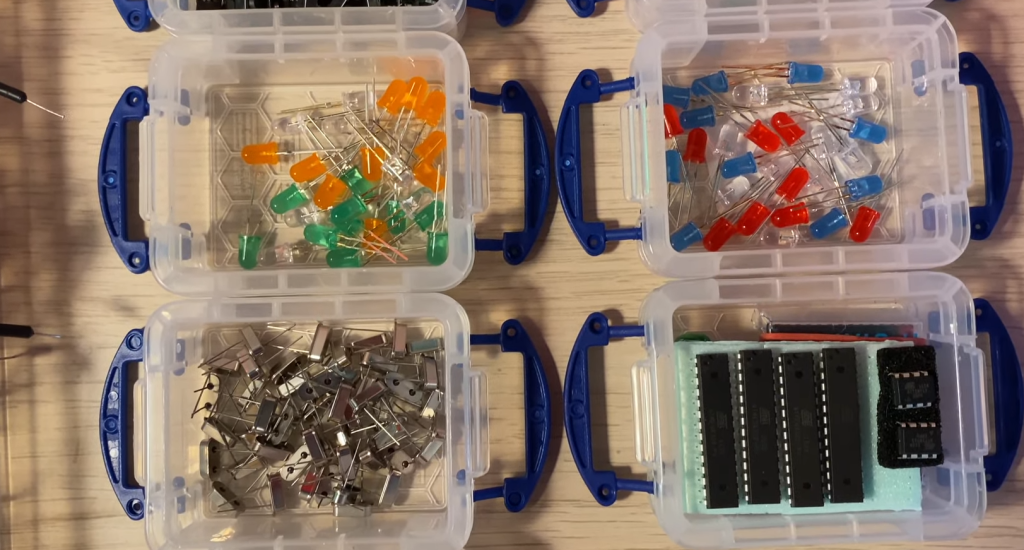
Hardware Components Needed:
- Arduino Board: You’ll need an Arduino board, such as an Arduino Uno, Arduino Nano, or any compatible Arduino variant;
- Breadboard: Choose a breadboard large enough for your circuit, ensuring it has both bus strips and terminal strips for components;
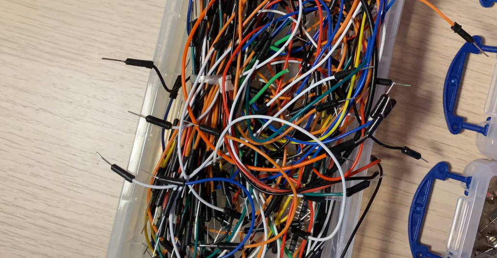
- Jumper Wires: You’ll need various jumper wires to connect components on the breadboard to the Arduino;
- Components for Your Project: Depending on your project, gather the specific components you require, such as LEDs, resistors, sensors, or any other electronic components;
- Power Supply: Ensure you have a suitable power supply for your Arduino, which can be a USB cable connected to a computer or a dedicated power adapter;
Hardware Assembly and Configurations:
1. Place the Arduino on the Breadboard
Carefully place your Arduino board on the breadboard so that the Arduino’s pins straddle the central groove of the breadboard. This will allow you to connect components to both sides of the breadboard.
2. Connect the Power Rails:
- Use jumper wires to connect the 5V pin on the Arduino to the “+” (positive) bus strip on one side of the breadboard;
- Connect the GND (Ground) pin on the Arduino to the “-“ (negative) bus strip on the same side of the breadboard. This provides power and ground connections to the entire breadboard;
3. Connect Components
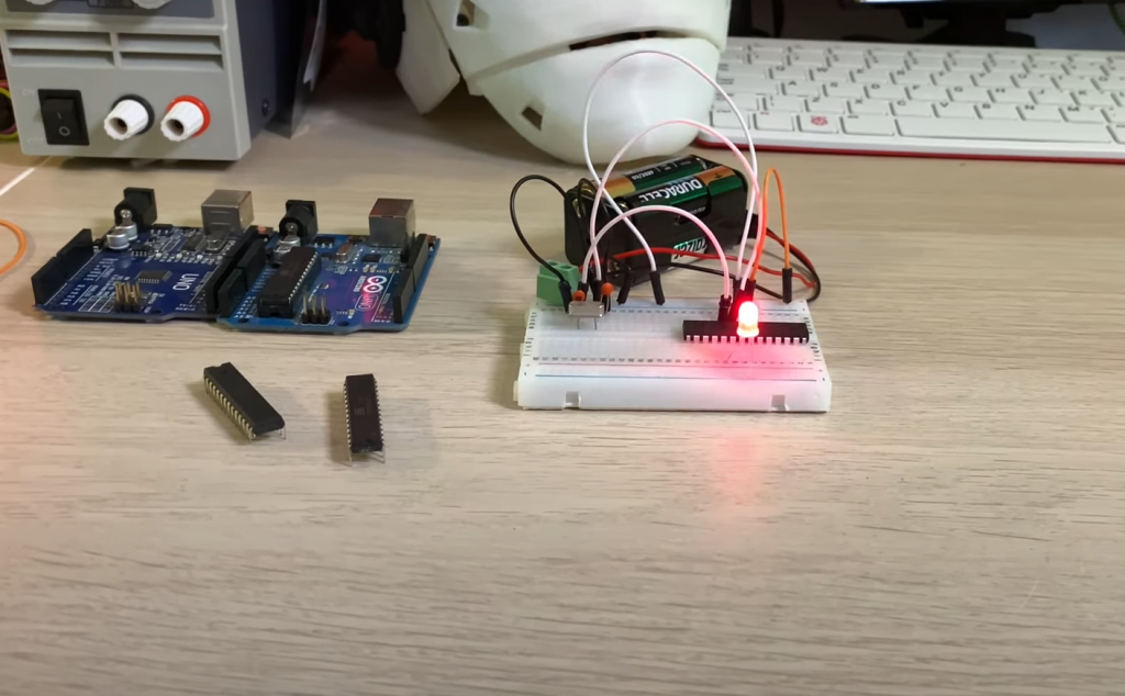
Depending on your project, start connecting components to the breadboard. For example, if you’re using an LED:
- Insert the longer (positive) lead of the LED into one row on the breadboard, and the shorter (negative) lead into an adjacent row;
- Connect a current-limiting resistor (e.g., 220-330Ω) to the same row as the LED’s negative lead.
- Connect one end of the resistor to the GND bus strip on the breadboard;
- Use a jumper wire to connect the other end of the resistor to a digital pin on the Arduino (e.g., Pin 13) [9];
4. Complete the Circuit
If your project involves more components, continue connecting them to the breadboard, making sure to complete the necessary electrical connections.
5. Double-Check Connections
Before proceeding, double-check all your connections to ensure there are no loose wires or unintended shorts.
Software Configurations and Arduino Code
Once your breadboard circuit is assembled, you’ll need to configure the software on your computer and upload code to the Arduino.
Here’s how:
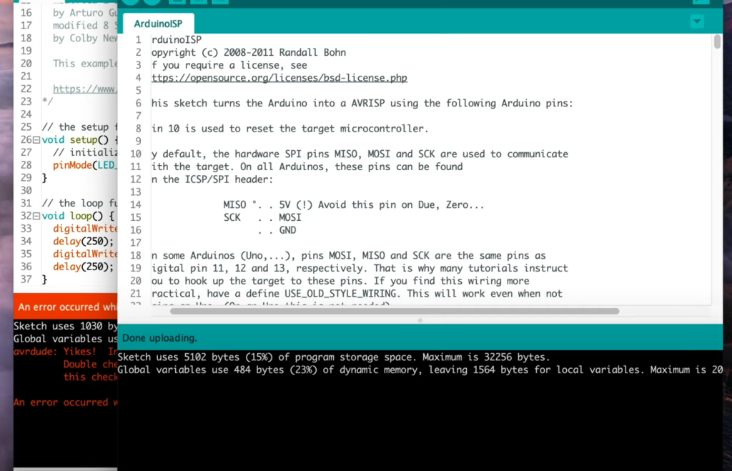
1. Install the Arduino IDE
If you haven’t already, download and install the Arduino Integrated Development Environment (IDE) on your computer from the official Arduino website.
2. Connect Your Arduino
Use a USB cable to connect your Arduino board to your computer.
3. Write or Load Arduino Code
Write your Arduino code in the Arduino IDE, or load an existing example sketch. Ensure that your code is tailored to your circuit and uses the appropriate pin configurations.
Compile and Upload
Click the “Upload” button in the Arduino IDE to compile your code and upload it to the Arduino board.
Test Your Circuit
After uploading the code, observe your breadboard circuit to see if it behaves as expected. For example, if you’re using an LED, it should light up according to your code.
Building a breadboard circuit with an Arduino is an excellent way to learn electronics and create a wide range of projects, from simple LED blinkers to more complex sensor-based systems. Once you have mastered the basics, you can explore more advanced circuits and expand your knowledge of Arduino-based electronics.
FAQ:
1. Can you put an Arduino on a breadboard?
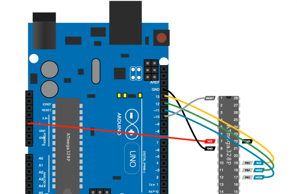
Yes, you can place and use an Arduino on a breadboard. However, you typically don’t put the entire Arduino board on the breadboard. Instead, you might place the ATmega microcontroller chip from the Arduino on the breadboard and connect it to external components to create a custom circuit. This is commonly done for prototyping or for creating custom Arduino-based projects.
2. Do you need a breadboard for Arduino?
While you don’t necessarily need a breadboard for every Arduino project, it is a valuable tool for prototyping and testing circuits. Breadboards allow you to quickly and easily connect and disconnect components, making it simpler to experiment with different configurations. For more permanent or compact projects, you might transition to custom PCBs (Printed Circuit Boards) or perfboards.
3. When should you not use a breadboard?
You should avoid using a breadboard in the following situations:
- High-Frequency Circuits: Breadboards are not suitable for high-frequency or RF (Radio Frequency) circuits due to their inherent parasitic capacitance and inductance;
- High-Current Applications: Breadboards have limited current-carrying capabilities and can overheat or cause voltage drops in high-current applications;
- Permanent Projects: For long-term or permanent projects, consider transitioning to custom PCBs or perfboards for reliability and durability;
- Sensitive Analog Circuits: Breadboards may introduce noise and impedance variations in sensitive analog circuits;
- Safety-Critical Systems: Avoid using breadboards for systems where reliability and safety are paramount, such as medical devices or aerospace applications;
4. Can a breadboard handle 12V?
Breadboards are typically designed for low-voltage circuits, such as those operating at 5V or below. Using 12V on a breadboard can exceed its voltage rating and may cause damage. It’s essential to check the specifications of your specific breadboard to determine its voltage limits.
5. How much power can a breadboard handle?
The power-handling capacity of a breadboard depends on various factors, including the design of the breadboard and the thickness of its internal traces. Typically, breadboards are suitable for low-power circuits, such as those operating at milliwatts to a few watts [10]. Exceeding these power limits can lead to overheating and damage to the breadboard.
6. Is ESP32 breadboard friendly?
Yes, the ESP32 is breadboard-friendly. It comes in a dual in-line package (DIP) module and has pins spaced at a standard 0.1-inch (2.54 mm) pitch, making it easy to insert into a breadboard for prototyping and development.
7. Is there a breadboard simulator?
Yes, there are several breadboard simulator software tools available that allow you to design and test circuits virtually before building them on a physical breadboard. Examples include Fritzing, Tinkercad, and Autodesk Eagle.
8. How big is a half-size breadboard?
A half-size breadboard typically measures around 83.8 mm (3.29 inches) in length and 53.3 mm (2.10 inches) in width. It provides a compact prototyping area while being compatible with standard 0.1-inch pitch components.
9. What is the size wire for an Arduino breadboard?
For most Arduino breadboard projects, it’s common to use jumper wires with male or female Dupont connectors on each end. These wires are typically available in various lengths, such as 20cm (8 inches) or 30cm (12 inches), and can be easily connected to the pins on both the Arduino board and the breadboard.
10. What is the voltage of an Arduino breadboard?
The voltage on an Arduino breadboard circuit depends on the specific components and power supply used. Arduino boards typically operate at 5V, but you can adapt the voltage according to your project’s requirements, such as using external voltage regulators.
11. Can I cut a breadboard?
Yes, you can cut a breadboard to customize its size or shape for your project. Be cautious when cutting, and ensure that you do not damage the internal metal traces or create unintended connections between rows or columns.
12. How long can a breadboard last?
The lifespan of a breadboard depends on usage and quality. With proper care and use within its specified limits, a breadboard can last for many years. However, overuse, excessive bending of wires, or high-current applications can shorten its lifespan.
13. Is the breadboard power supply AC or DC?
A breadboard’s power supply is typically DC (Direct Current). It is commonly used for low-voltage DC circuits, such as those powered by batteries, USB adapters, or DC power sources.
14. Can breadboards handle AC?
Breadboards are primarily designed for DC (Direct Current) circuits. While you can use breadboards for AC signals at low frequencies, it’s essential to consider their limitations, such as potential impedance and noise issues, especially at higher frequencies. For AC circuits or high-frequency applications, custom PCBs or specialized prototyping boards may be more suitable.
Useful Video: Make your own Arduino on a breadboard
References:
- https://docs.arduino.cc/hacking/hardware/building-an-arduino-on-a-breadboard
- https://www.instructables.com/How-to-Build-an-Arduino-Uno-on-a-BreadBoard/
- https://www.seeedstudio.com/blog/2020/01/06/how-to-use-a-breadboard-wiring-circuit-and-arduino-interfacing/
- https://www.electronics-lab.com/project/arduinoatmega328p-on-a-breadboard/
- https://www.homemade-circuits.com/make-arduino-breadboard/
- https://www.digikey.com/en/maker/projects/build-your-own-arduino-breadboard/f243b09293ae4e3189bda47a821bb97a
- https://linuxhint.com/breadboard-arduino/
- https://www.geekering.com/categories/embedded-sytems/arduino/bruno-silva/arduino-uno-on-a-breadboard/
- https://duino4projects.com/build-arduino-circuit-breadboard/
- https://www.the-diy-life.com/build-your-own-arduino-on-a-breadboard/