Arduino, an open-source electronics platform, is transforming the world of automation with its versatility and ease of use. One such application is controlling a linear actuator – a device that moves in a straight line and is used extensively in machine tools, computer peripherals, and other industrial applications.
This article provides an in-depth look at how to control a linear actuator using Arduino. We’ll explore how to use relays and Arduino programming to manipulate the movement, position, and force of a linear actuator. Whether you’re a seasoned engineer or a hobbyist, this guide will empower you to bring your automation projects to life.
What Is An Arduino?
The beauty of Arduino lies in its accessibility – it’s designed to be user-friendly, making it a valuable tool for beginners and experts alike.
Arduino boards come in different shapes and sizes, but they all share the same core functionalities. They are equipped with input and output pins, memory for storing code, and a central processing unit (CPU). The heart of an Arduino is its software, which can be easily programmed using the Arduino Integrated Development Environment (IDE).
The IDE features a simplified coding language, based on C/C++, which allows users to create custom programs, or “sketches”, to control the board’s behavior.
Arduino has revolutionized the world of hobbyists, makers, and professionals by providing an affordable and accessible way to bring electronic projects to life. From home automation to robotics, from weather stations to interactive art installations, Arduino can be adapted to serve an endless array of applications.
What Is A Linear Actuator?
A linear actuator is a mechanical device that converts rotary motion (circular movement) into linear motion (straight-line movement).
This fundamental transformation is essential for numerous applications where precise linear movement is required, such as in robotics, automotive systems, industrial machinery, and more.
At its core, a linear actuator consists of three main components:
- Input Shaft or Motor: This is the component that provides the initial rotary motion. It can be an electric motor, a hand crank, or any other mechanism that generates rotational force;
- Conversion Mechanism: The input shaft’s rotational motion is transformed into linear motion through various methods, depending on the type of linear actuator. This could involve screws, gears, belts, or even direct-drive systems;
- Output Shaft: The output shaft is what moves in a linear fashion as a result of the conversion mechanism. It’s typically attached to the load that needs to be moved, whether it’s a door, a valve, a camera, or any other object [2];
Linear actuators come in a variety of sizes, shapes, and designs to cater to specific needs. Some are compact and suitable for micro-adjustments, while others are powerful and capable of moving heavy loads over substantial distances.
Why Use an Arduino to Control a Linear Actuator?
Precision and Customization
One of the primary advantages of using an Arduino to control a linear actuator is precision. Arduino’s programmability allows you to control the actuator’s movement with incredible accuracy. Whether you need to move an object a fraction of an inch or several feet, you can program the Arduino to achieve the desired level of precision.
Moreover, Arduino enables customization. You can create tailored control algorithms that respond to specific inputs, conditions, or triggers. For instance, you can integrate sensors like ultrasonic distance sensors, infrared detectors, or pressure sensors to make your linear actuator respond intelligently to its environment.
Versatility and Flexibility
Arduino’s versatility shines when it comes to controlling linear actuators. It can seamlessly integrate with a wide range of sensors and peripheral devices, allowing you to create complex automation systems. This flexibility is crucial in applications where the linear actuator needs to interact with other components or respond to changing conditions.
User-Friendly Programming
Arduino’s user-friendly programming environment makes it accessible to beginners while offering advanced capabilities for experienced users. The Arduino IDE provides an intuitive interface for writing, uploading, and debugging code. The vast Arduino community contributes libraries, code examples, and forums where you can find solutions to common problems or seek assistance with your projects.

Cost-Effective Solution
Arduino boards are affordable, making them an attractive choice for budget-conscious projects. Combining a low-cost Arduino with a linear actuator can result in a cost-effective automation solution, especially when compared to proprietary control systems.
How Does A Linear Actuator Work?
Mechanical Transformation
At its core, a linear actuator is a mechanical transformer. It takes an input motion (typically rotary) and converts it into linear motion.
The method used for this transformation depends on the type of linear actuator:
- Screw-Driven Actuators: These actuators use a threaded screw mechanism. As the screw rotates, it moves a nut along its threads, causing linear motion of the nut and any attached load;
- Gear-Driven Actuators: Gear-driven actuators employ a set of gears to convert rotary motion into linear motion. The arrangement of gears determines the direction and speed of linear movement;
- Belt-Driven Actuators: In this type of actuator, a belt connects the input shaft (usually a pulley) to the output shaft (a carriage or platform). As the pulley rotates, the belt moves, resulting in linear displacement;
- Piezoelectric Actuators: Piezoelectric materials change shape when subjected to an electric field, allowing for precise and rapid linear motion;
- Hydraulic and Pneumatic Actuators: These actuators use pressurized fluids (hydraulic fluid or compressed air) to generate linear movement. By controlling the flow and pressure of the fluid, you can control the actuator’s motion [3];
Control Signals
For an Arduino to control a linear actuator, it must send the appropriate control signals to the actuator’s input mechanism.
This typically involves applying electrical voltage or current to the actuator’s motor or drive system:
- Voltage Control: Many linear actuators are designed to operate using a specific voltage range. By varying the voltage applied to the actuator, you can control its speed and direction. Arduino can generate analog voltage signals to achieve this;
- Pulse-Width Modulation (PWM): PWM is a technique where the Arduino rapidly switches a signal on and off. By varying the width of the on-time (duty cycle), you can control the average voltage applied to the actuator, thus controlling its speed and position;
- Direction Control: In addition to controlling speed, Arduino can also control the direction of the linear actuator’s movement by toggling the direction pins;
Types Of Linear Actuators
1. Electric Linear Actuators
Electric linear actuators are perhaps the most popular and widely used type. They are versatile, efficient, and suitable for both small-scale and large-scale applications.
Electric linear actuators can be further categorized into subtypes, such as:
- Screw-Driven Actuators: These use a screw mechanism to produce linear motion. They are precise and commonly used in applications where accuracy is crucial;
- Belt-Driven Actuators: Belt-driven actuators are known for their smooth and quiet operation. They are often used in situations where noise is a concern;
2. Hydraulic Linear Actuators
Hydraulic linear actuators utilize pressurized hydraulic fluid to generate linear motion. They are known for their high force output and are commonly found in heavy machinery and industrial applications.
3. Pneumatic Linear Actuators
Pneumatic linear actuators use compressed air to create linear motion. They are lightweight, cost-effective, and suitable for tasks that require rapid and repetitive motion.
4. Piezoelectric Actuators
Piezoelectric actuators are known for their precision and ability to provide nanometer-scale positioning. They are commonly used in applications like microscopy and semiconductor manufacturing.
5. Linear Solenoids
Linear solenoids work by converting electrical energy into linear mechanical motion. They are used in various applications, including lock systems, medical devices, and automotive components.
6. Rack and Pinion Actuators
Rack and pinion actuators use a gear mechanism to convert rotary motion into linear motion. They are commonly used in automotive steering systems and industrial machinery.
Each type of linear actuator has its own strengths and weaknesses, making it important to choose the one that best suits your specific project or application.
Peculiarities Of Controlling a Linear Actuator With Arduino:
Relays: Managing High-Current Applications
Relays are indispensable components when dealing with high-current applications, such as controlling linear actuators that draw substantial power. These electromechanical switches allow the Arduino to control devices that require more current or voltage than the Arduino pins can handle directly.
How do Relays Work?
Relays consist of an electromagnet, an armature (a movable contact), and a set of fixed contacts. When a small electrical current flows through the coil of the relay (controlled by an Arduino pin), it generates a magnetic field that pulls the armature. This movement of the armature can either connect or disconnect the fixed contacts, allowing or interrupting the flow of a larger current.
Using Relays To Control Linear Actuators
When using a relay to control a linear actuator, you typically connect the actuator’s power supply (the high-current source) to the common terminal of the relay. The normally open (NO) or normally closed (NC) terminals are then connected to the actuator’s power input. By energizing or de-energizing the relay coil with an Arduino pin, you can effectively turn the linear actuator on or off [4].
Here’s a simplified example of how to control a linear actuator with a relay and Arduino:
#include
// Define relay control pin
const int relayPin = 2; // Digital pin connected to the relay
void setup() {
// Set relay control pin as an output
pinMode(relayPin, OUTPUT);
}
void loop() {
// Activate the relay (turn on the linear actuator)
digitalWrite(relayPin, HIGH);
// Delay for a few seconds (or perform other tasks)
delay(5000); // Delay for 5 seconds
// Deactivate the relay (turn off the linear actuator)
digitalWrite(relayPin, LOW);
// Delay before reactivation (or perform other tasks)
delay(2000); // Delay for 2 seconds
}
Using a relay in this manner provides a high level of isolation between the Arduino and the linear actuator’s high-current circuit, ensuring safety and reliability.
Motor Driver: Precise Control of Direction and Speed
For more advanced control of linear actuators, especially those with bidirectional movement and variable speed requirements, motor drivers are essential. Motor drivers enable precise control of both the direction and speed of the actuator’s motion.
How Does Motor Drivers Work?
Motor drivers, often based on integrated circuits (ICs) like the L298N or L293D, can handle higher currents and voltages than the Arduino pins. They contain H-bridges, which allow the motor to be driven in both forward and reverse directions.
Using a Motor Driver with Arduino
To control a linear actuator using a motor driver and Arduino, you’ll need to connect the motor driver’s input pins to the Arduino. Typically, there are four control pins for each motor (two for direction and two for speed control). By manipulating these pins through the Arduino, you can achieve precise control over the actuator’s movement.
Here’s a simplified example of controlling a linear actuator with a motor driver and Arduino:
#include <Arduino.h>
// Define motor control pins
const int motorIN1 = 2; // Motor driver input pin 1 (direction)
const int motorIN2 = 3; // Motor driver input pin 2 (direction)
const int motorPWM = 9; // Motor driver PWM pin (speed control)
void setup() {
// Set motor control pins as outputs
pinMode(motorIN1, OUTPUT);
pinMode(motorIN2, OUTPUT);
pinMode(motorPWM, OUTPUT);
}
void loop() {
// Move the linear actuator forward
digitalWrite(motorIN1, HIGH); // Set direction
digitalWrite(motorIN2, LOW);
analogWrite(motorPWM, 255); // Set speed (0 to 255 for variable speed)
// Delay for a few seconds (or perform other tasks)
delay(5000); // Delay for 5 seconds
// Stop the linear actuator
digitalWrite(motorIN1, LOW); // Set direction to stop
digitalWrite(motorIN2, LOW);
analogWrite(motorPWM, 0); // Set speed to 0
// Delay before reversing (or perform other tasks)
delay(2000); // Delay for 2 seconds
}
Motor drivers provide greater control over the linear actuator’s movement, including variable speed adjustment and bidirectional motion [5].
Adding Inputs: Enhancing Control and Automation
To create more sophisticated and interactive applications, it’s often necessary to add inputs to your Arduino-linear actuator control system. Inputs can include sensors, switches, or other devices that provide data or trigger specific actions.
Types of Inputs:
- Limit Switches: These are commonly used to detect the endpoints of linear actuator travel. When the actuator reaches a limit, the switch is triggered, and the Arduino can stop the actuator’s movement to prevent overextension or damage;
- Potentiometers: Potentiometers can be used to provide analog feedback on the position of the linear actuator. This feedback can be used to implement position control algorithms;
- Ultrasonic Sensors: Ultrasonic distance sensors can be employed to detect the presence or proximity of objects. This can be useful in applications where the actuator needs to respond to its surroundings;
- Pressure Sensors: Pressure sensors can be used in applications where the linear actuator needs to exert a specific force or respond to changes in pressure;
- Infrared (IR) Sensors: IR sensors can be used for object detection and tracking, making them valuable in automation and robotics applications;
Incorporating Inputs into Your Control System
To add inputs to your Arduino-linear actuator system, you’ll need to connect the sensors or switches to the appropriate Arduino pins. Then, you can write code to read the sensor data and make decisions based on that data.
Here’s an example of using a limit switch as an input to stop the linear actuator when it reaches the end of its travel:
#include <Arduino.h>
// Define linear actuator control pins
const int motorIN1 = 2; // Motor driver input pin 1 (direction)
const int motorIN2 = 3; // Motor driver input pin 2 (direction)
const int motorPWM = 9; // Motor driver PWM pin (speed control)
// Define limit switch pin
const int limitSwitchPin = 4; // Digital pin for the limit switch
void setup() {
// Set motor control pins as outputs
pinMode(motorIN1, OUTPUT);
pinMode(motorIN2, OUTPUT);
pinMode(motorPWM, OUTPUT);
// Set limit switch pin as an input
pinMode(limitSwitchPin, INPUT_PULLUP);
}
void loop() {
// Check the status of the limit switch
if (digitalRead(limitSwitchPin) == LOW) {
// Limit switch is triggered, stop the linear actuator
digitalWrite(motorIN1, LOW); // Set direction to stop
digitalWrite(motorIN2, LOW);
analogWrite(motorPWM, 0); // Set speed to 0
} else {
// Move the linear actuator forward
digitalWrite(motorIN1, HIGH); // Set direction
digitalWrite(motorIN2, LOW);
analogWrite(motorPWM, 255); // Set speed (0 to 255 for variable speed)
}
}
In this example, the limit switch input is used to stop the linear actuator when it reaches the limit of its travel.
By incorporating inputs like limit switches, you can add safety features and automation capabilities to your linear actuator control system.
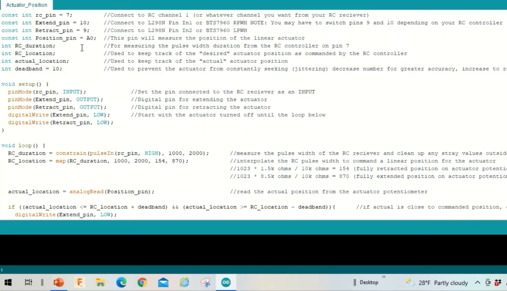
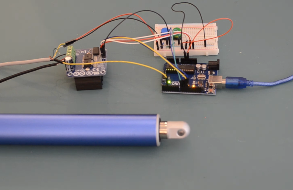
How To Control Linear Actuator:
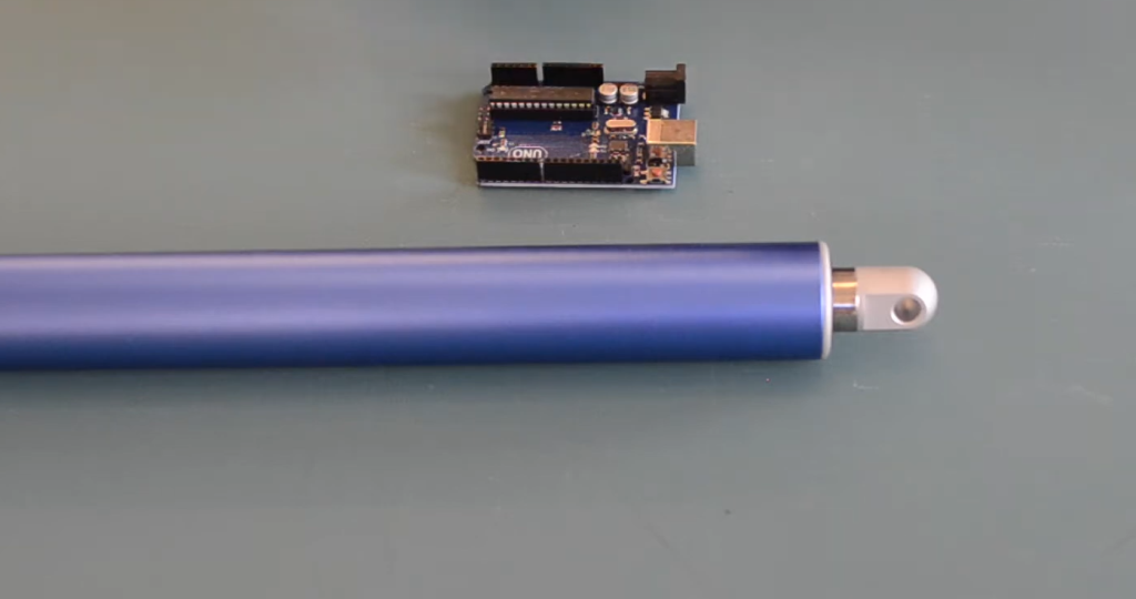
Components:
- Linear Actuator: This represents your linear actuator, which typically has two wires for power (positive and negative) and sometimes additional wires for feedback or limit switches;
- Power Supply: Connect the power supply to the linear actuator. Make sure the voltage and current rating of the power supply match the requirements of your actuator;
- L298N Motor Driver: The L298N motor driver is a popular choice for controlling linear actuators. It provides the necessary H-bridge circuitry for bidirectional control and speed regulation;
- Arduino Board: Connect the Arduino to the motor driver for sending control signals. Ensure a common ground connection between the Arduino, power supply, and motor driver [6];
Motor Driver Connections:
- IN1 and IN2: These pins control the direction of the actuator. To make it extend, set one pin high and the other low; to retract, reverse their states;
- ENA and ENB: These pins control the speed of the motor. Applying PWM (Pulse-Width Modulation) to ENA or ENB allows you to adjust the speed;
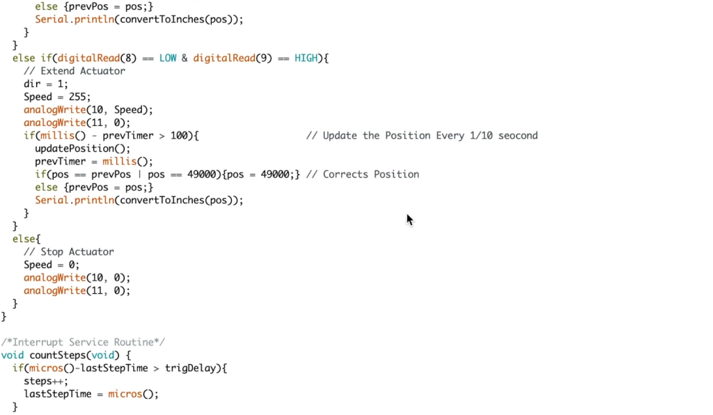
How To Make a Linear Actuator Expand/Retract?
Expanding or retracting a linear actuator involves controlling the direction of movement. This is achieved by setting the appropriate pins (IN1 and IN2) on the motor driver high or low.
Here’s a simplified example using an Arduino:
#include <Arduino.h>
// Motor driver pins
const int motorIN1 = 2; // Connected to IN1 on the motor driver
const int motorIN2 = 3; // Connected to IN2 on the motor driver
void setup() {
// Set motor control pins as outputs
pinMode(motorIN1, OUTPUT);
pinMode(motorIN2, OUTPUT);
}
void loop() {
// Extend the linear actuator
digitalWrite(motorIN1, HIGH); // Set one direction pin high
digitalWrite(motorIN2, LOW); // Set the other direction pin low
// You can add a delay for a specific time or use sensors/inputs to control when to stop.
// Retract the linear actuator
digitalWrite(motorIN1, LOW); // Set one direction pin low
digitalWrite(motorIN2, HIGH); // Set the other direction pin high
// You can add a delay for a specific time or use sensors/inputs to control when to stop.
}
In this example, by changing the states of motorIN1 and motorIN2, you can make the linear actuator extend and retract. However, for more precise control and automation, you may want to incorporate limit switches or sensors to stop the actuator at specific positions.
How To Stop Linear Actuators from Extending or Retracting?
Stopping a linear actuator’s motion can be achieved in a few ways:
- Using Limit Switches: Limit switches are sensors placed at the ends of the actuator’s travel path. When the actuator’s moving part (e.g., a rod) comes into contact with the limit switch, it triggers a signal to stop the actuator. Connect the limit switch to your control circuit and program the Arduino to respond to the switch’s signal;
- Using Sensors: You can use various sensors (e.g., ultrasonic sensors, IR sensors) to detect objects or obstacles and stop the actuator when it approaches a certain threshold. The Arduino can read data from these sensors and act accordingly;
- Using Timers or Delays: You can incorporate delays or timers in your Arduino code to control how long the actuator extends or retracts. This method is simple but less precise than using sensors or limit switches;
How to Control Linear Actuators with Relays and Arduino:
Linear actuators are versatile devices that can be used in various applications, from opening doors to adjusting camera positions. When it comes to controlling linear actuators, using relays with an Arduino is a practical and cost-effective solution.
Choosing the Right Relay Module
Selecting the appropriate relay module is crucial for ensuring a reliable and safe linear actuator control system.
Here are some key considerations when choosing a relay module:
- Voltage and Current Ratings: Ensure that the relay module can handle the voltage and current requirements of your linear actuator. Check the actuator’s datasheet for this information;
- Number of Relays: Determine how many linear actuators you need to control. Choose a relay module with the appropriate number of relays to match your project’s requirements;
- Type of Relay: Opt for a relay type suitable for DC (Direct Current) applications since linear actuators typically operate on DC voltage. Some relay modules are designed specifically for DC loads;
- Control Voltage: Confirm that the relay module is compatible with the control voltage provided by your Arduino. Arduino boards usually use 5V or 3.3V for digital outputs;
- Additional Features: Some relay modules come with additional features like opto-isolation, status LEDs, and protection diodes. These features can enhance the performance and reliability of your setup;
Once you’ve selected the right relay module based on these considerations, you’re ready to connect it to your Arduino and linear actuator.
Connecting Relay to Arduino
The connection between the relay module and Arduino is relatively straightforward. Relay modules typically have three sets of pins: input pins (for control), common pins, and normally open (NO) or normally closed (NC) contacts for the load.
Here’s how to connect the relay module to an Arduino:
1. Input Pins:
Relay modules often have an input pin labeled “IN” or “Signal”. Connect this pin to one of the digital output pins on your Arduino. The choice of the pin number is up to you, but make sure to note which pin you’ve used in your Arduino code.
2. Common Pins:
There are usually two common pins on the relay module, labeled “COM” or “Common”. Connect one of these common pins to the ground (GND) pin on your Arduino. This establishes a common ground reference between the Arduino and the relay module.
3. Load Pins:
The relay module also has load pins, which are often labeled “NO” (Normally Open) and “NC” (Normally Closed). For controlling a linear actuator, connect the “NO” (Normally Open) pin to one side of your actuator, and connect the other side of the actuator to the positive terminal of your power supply. The negative terminal of the power supply should be connected to the ground (GND) on your Arduino.
4. Power Supply:
Ensure that the power supply for your linear actuator provides the necessary voltage and current. Connect the power supply’s positive terminal to the other side of the linear actuator, and the negative terminal to the ground (GND) on your Arduino, completing the circuit.
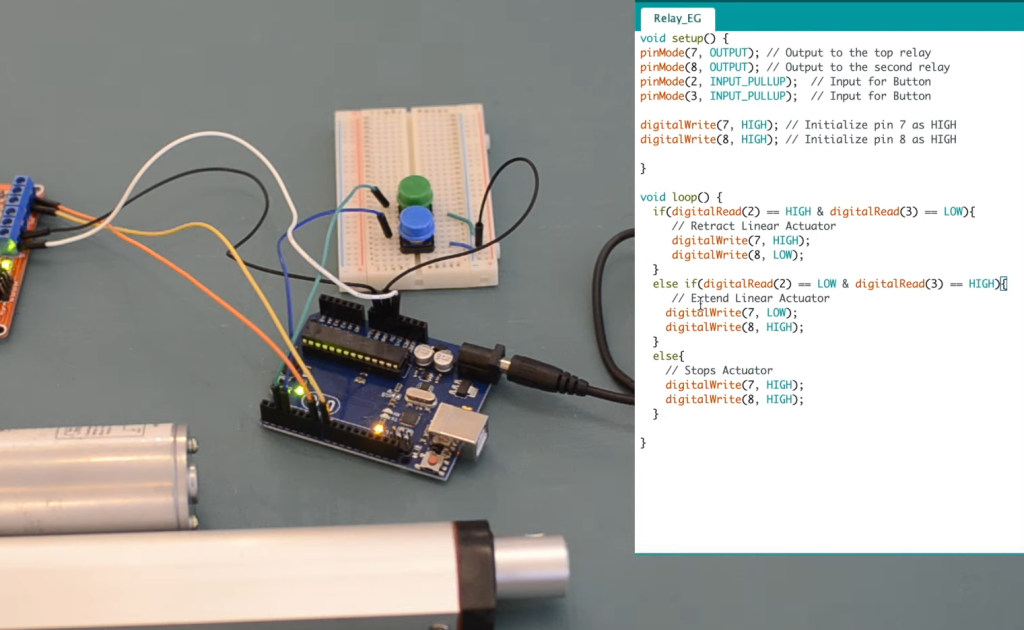
Linear Actuator Relay Wiring
With the relay module connected to your Arduino and linear actuator, your wiring setup should look something like this:
- Arduino Pin: Connect the “IN” or “Signal” pin on the relay module to one of the digital output pins on your Arduino (e.g., digital pin 7);
- Common (COM): Connect one of the “Common” pins on the relay module to the ground (GND) pin on your Arduino;
- Linear Actuator: Connect the “NO” (Normally Open) pin on the relay module to one side of your linear actuator. Connect the other side of the actuator to the positive terminal of your power supply;
- Power Supply: Connect the negative terminal of the power supply to the ground (GND) pin on your Arduino to establish a common ground reference;
Here’s a simplified example of Arduino code to control the linear actuator using the relay module:
#include <Arduino.h>
const int relayPin = 7; // Digital pin connected to the relay module
void setup() {
pinMode(relayPin, OUTPUT);
}
void loop() {
// Extend the linear actuator
digitalWrite(relayPin, HIGH); // Turn on the relay
// Delay for a few seconds or perform other tasks
delay(5000); // Delay for 5 seconds
// Retract the linear actuator
digitalWrite(relayPin, LOW); // Turn off the relay
// Delay before the next action or perform other tasks
delay(5000); // Delay for 5 seconds
}
In this code, when the relay pin (connected to the digital pin 7) is set to HIGH, the relay closes, allowing current to flow through the linear actuator, causing it to extend. When the relay pin is set to LOW, the relay opens, stopping the actuator. You can customize the timing and sequence of actuator movements in your code according to your project’s requirements.
FAQ:
1. Can Arduino control a linear actuator?
Yes, Arduino can control a linear actuator. By using suitable control methods, such as relays, motor drivers, or H-bridge circuits, you can connect a linear actuator to an Arduino and program it to control the actuator’s direction, speed, and position.
2. How do you control the speed of a linear actuator in Arduino?
To control the speed of a linear actuator in Arduino, you can use a pulse-width modulation (PWM) signal. Connect the PWM-capable pin of your Arduino to the enable (EN) or speed control input of a motor driver or H-bridge circuit that is controlling the linear actuator. By varying the PWM duty cycle, you can adjust the speed of the actuator.
3. How do you control 4 linear actuators?
To control four linear actuators simultaneously, you will need a microcontroller with enough digital output pins and motor drivers or relay modules for each actuator. Connect each linear actuator to its respective driver or relay, and control them independently through the Arduino by writing code to address each actuator’s pins.
4. How do you program a linear actuator?
Programming a linear actuator involves writing code for an Arduino or other microcontroller to send control signals to the actuator. You specify the direction, speed, and position you want the actuator to achieve in your code. The actuator’s control method (e.g., relay, motor driver) determines the specifics of the programming.
5. How to control the speed of a linear actuator using an Arduino?
To control the speed of a linear actuator using an Arduino, connect the Arduino’s PWM-capable pin to the speed control input of a motor driver or H-bridge circuit that controls the actuator. Use the analogWrite() function in your Arduino code to set the PWM value, which will determine the actuator’s speed.
6. How do you control a linear actuator with a switch?
You can control a linear actuator with a switch by wiring the switch in series with the actuator’s power supply. When you toggle the switch, it either completes or interrupts the circuit, turning the actuator on or off. This method provides basic control but lacks the ability to regulate speed or position.
7. Do you need a controller for a linear actuator?
Yes, you typically need a controller to operate a linear actuator effectively. The controller can be an Arduino or another microcontroller that sends signals to the actuator, specifying its movement and behavior. The controller interprets user input or sensor data and translates it into control commands for the actuator.
8. How do you control a 12V linear actuator?
To control a 12V linear actuator, you need a power supply that provides a stable 12V DC voltage. You can use an Arduino or a microcontroller to control the actuator’s direction, speed, and position by interfacing it with suitable motor drivers or relays.
9. Are linear actuators AC or DC?
Linear actuators can be designed to operate on both AC (Alternating Current) and DC (Direct Current) power sources. However, the majority of linear actuators used in small to medium-sized applications, especially in robotics and automation, are DC-powered.
10. Do linear actuators push or pull?
Linear actuators can either push or pull, depending on their design and configuration. Some actuators extend (push), while others retract (pull). The direction of motion depends on the polarity of the voltage applied and the actuator’s mechanical setup.
11. How do you power a linear actuator?
Linear actuators are powered by a DC voltage source, typically 12V or 24V, although other voltage ratings are also available. The power supply should match the actuator’s voltage and current requirements, and it should be connected to the actuator’s power terminals.
12. Can you control the speed of a linear actuator?
Yes, you can control the speed of a linear actuator by adjusting the input voltage or using pulse-width modulation (PWM). PWM is a common method as it allows precise speed control by varying the duty cycle of the signal.
13. How to control speed using Arduino?
To control the speed using Arduino, you can connect the Arduino’s PWM-capable pin to the speed control input of a motor driver or actuator controller. Use the analogWrite() function to adjust the PWM duty cycle, which will regulate the speed.
14. Can an Arduino power a linear actuator?
An Arduino cannot directly power a linear actuator, as it doesn’t provide sufficient voltage or current. However, an Arduino can control a linear actuator by sending signals to a motor driver or relay module that manages the actuator’s power supply.
15. How do linear actuators fail?
Linear actuators can fail due to various reasons, including overloading, overheating, mechanical wear and tear, electrical faults, or insufficient maintenance. Failures may result in issues such as loss of motion, erratic movement, or physical damage to the actuator components.
16. How much power does a linear actuator use?
The power consumption of a linear actuator depends on its voltage rating and current draw. Actuators are typically rated in watts (W) or milliwatts (mW). To calculate power (P), use the formula: P = Voltage (V) x Current (I). Ensure that your power supply can provide the necessary power for the actuator’s operation.
17. Can linear actuators rotate?
Linear actuators are designed for linear motion and cannot rotate on their own. However, some specialized designs, such as worm gear actuators, can achieve limited rotational movement when connected to a rotary device or mechanism.
18. Is a linear actuator better than a pneumatic one?
The choice between a linear actuator and a pneumatic actuator depends on the specific application and requirements. Linear actuators are precise, controllable, and suitable for various tasks. Pneumatic actuators, on the other hand, offer advantages like high force, fast operation, and resistance to harsh environments. The choice depends on factors such as load, speed, control, and environmental conditions.
Useful Video: Controlling a Linear Actuator with an Arduino and Relay
References:
- https://www.firgelliauto.com/blogs/tutorials/how-do-you-control-a-linear-actuator-with-an-arduino
- https://arduinogetstarted.com/tutorials/arduino-actuator
- https://www.progressiveautomations.com/blogs/how-to/how-to-use-an-arduino-with-linear-actuators
- https://www.instructables.com/Control-a-Large-Linear-Actuator-With-Arduino/
- https://www.progressiveautomations.com/blogs/how-to/how-to-use-relays-to-control-linear-actuators
- https://www.makerguides.com/driving-a-linear-actuator-using-an-arduino/