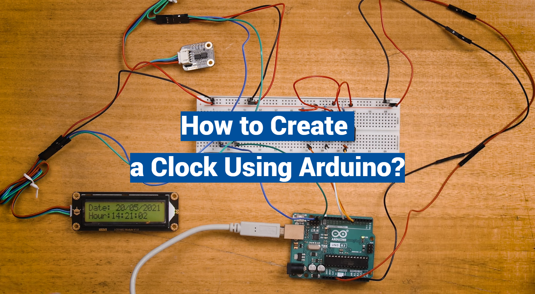
Welcome to the fascinating world of DIY electronics! In this comprehensive guide, we’ll delve into the procedure for creating a digital clock using an Arduino. This project is a wonderful blend of technology and practicality, allowing you to build your own time-keeping device from scratch.
Whether you’re an experienced hobbyist or a beginner looking to expand your skills, this project offers an excellent opportunity to understand the interaction between hardware and software.
We’ll explore everything from the necessary components, and wiring details, to coding essentials. So, let’s start our journey in crafting a functional, Arduino-based digital clock
How to Get the Current Date and Time on an Arduino?
Getting the current date and time on an Arduino can be achieved in several ways. Here are a few methods:
- Using the millis() function: This function returns the number of milliseconds passed since your Arduino board started running the current program. However, it only shows the time since the reboot of the Arduino;
- Using an external Real Time Clock (RTC) module: If you start the Arduino at a specific time, you can calculate the exact date and time using an RTC module;
- Using the DateTime library: You can sync the Arduino clock to the time received on the serial port using the DateTime library;
- Using the ESP32 with NTP Server: You can get the current date and time using the ESP32 microcontroller with an NTP server and the Arduino IDE [1];
It’s important to note that the best method will depend on your specific project requirements.
How Does the Arduino Alarm Clock Work?
Here’s a basic outline of how it works:
- Real-Time Clock (RTC) Module: The RTC module, often a DS3231 or similar, keeps track of the current time even when the Arduino is powered off. This module runs on a separate battery, ensuring that it keeps time accurately. It typically communicates with the Arduino through an I2C interface;
- User Input: Buttons are used to set the current time and alarm time. In some designs, additional buttons can be used to enable or disable the alarm;
- Alarm Functionality: The Arduino continuously compares the current time from the RTC module with the preset alarm time. When the current time matches the set alarm time, a signal is sent to trigger the alarm. This typically involves activating a buzzer or speaker;
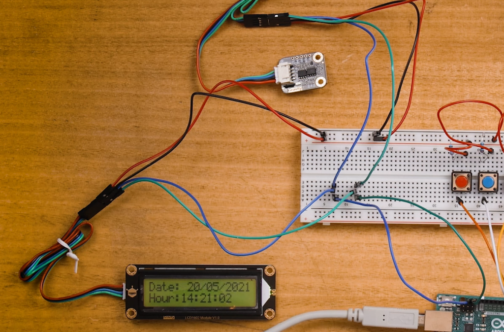
- Display: The current time and potentially the set alarm time are displayed on a screen, often an LCD;
Applications of Arduino Digital Clock
1. Bedroom Alarm Clock
A DIY Arduino alarm clock can serve as a customizable and unique addition to your bedroom. You can set your favorite alarm sounds, customize the display, and even integrate additional features like temperature and humidity monitoring [2].
2. Classroom Timer
In educational settings, Arduino digital clocks can be repurposed as classroom timers. Teachers can program the clock to count down to the end of a lesson or display important reminders for students.
3. Conference Room Scheduler
Arduino digital clocks can be used in corporate environments as conference room schedulers. The clock can display meeting schedules, and room availability, and even indicate when a room is in use.
4. Weather Station
By adding additional sensors, an Arduino digital clock can be transformed into a weather station. It can display real-time weather information such as temperature, humidity, and barometric pressure.
5. Kitchen Timer
In the kitchen, Arduino digital clocks can serve as timers for cooking and baking. You can program them to sound an alarm when your dish is ready.
6. Workshop Clock
For hobbyists and makers, an Arduino digital clock in the workshop can help keep track of project time and deadlines. It can also be integrated with other automation projects.
7. Art Installation
Arduino digital clocks can be used as artistic installations in galleries or public spaces. Their versatility allows artists to create unique time-related displays and interactive pieces.
Creating an Arduino Digital Clock: A Beginner’s Guide
About Parts:
- Arduino: The Arduino board is the heart of your digital clock project. Common choices include the Arduino Uno, Arduino Nano, or Arduino Mega. These boards provide the processing power and I/O pins needed to interact with other components;
- 16×2 LCD Display: A 16×2 Liquid Crystal Display (LCD) module is a widely used choice for displaying information in Arduino projects. It consists of 16 character columns and 2 rows, offering a simple and effective way to present text-based information like the time in our digital clock;
- I2C LCD Display Module: To simplify the connection between the Arduino and the 16×2 LCD display, an I2C (Inter-Integrated Circuit) LCD display module can be used. This module reduces the number of required pins and simplifies the wiring, making it ideal for beginners;
- DS1307 Real-Time Clock Module: The DS1307 Real-Time Clock (RTC) module is a crucial component for keeping accurate time in your digital clock. It communicates with the Arduino via I2C and maintains the date and time even when the Arduino is powered off. The DS1307 is known for its reliability and ease of use;
Assembling Your Digital Clock
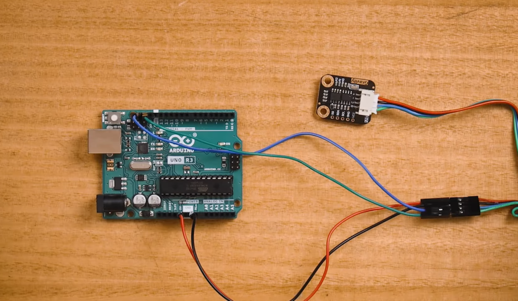
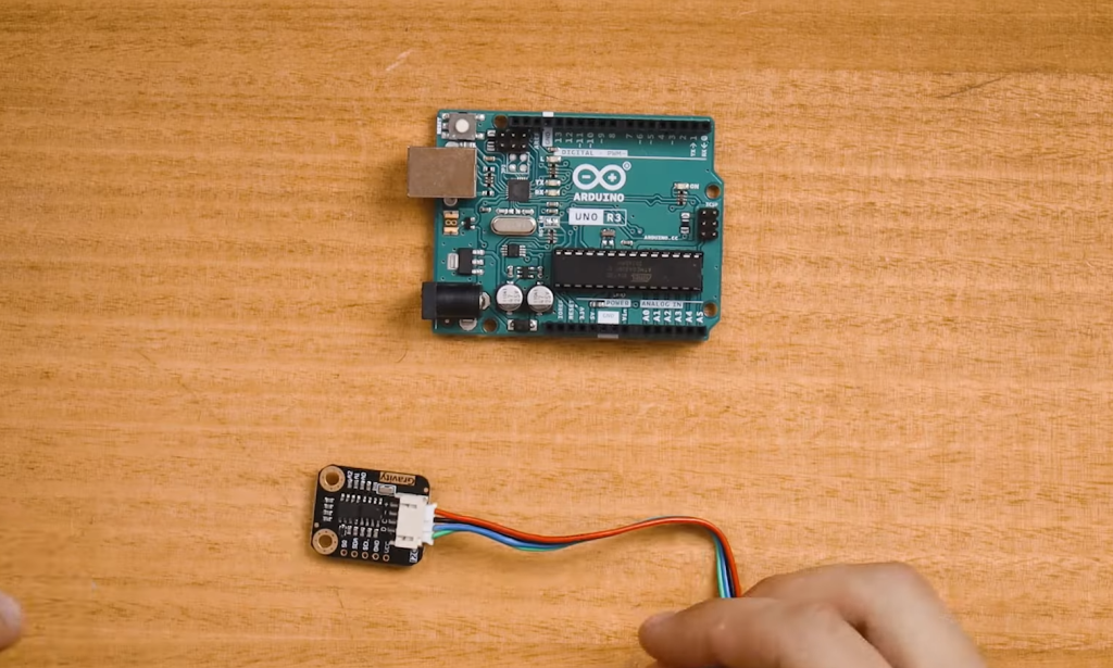
1. Gather Your Components
Ensure you have all the necessary components ready: the Arduino board, 16×2 LCD display, I2C LCD display module, and DS1307 RTC module. You’ll also need jumper wires for connections and a power source for your Arduino (USB cable or battery).
2. Connect the Components
Arduino to I2C LCD Module:
Connect the SDA (data) and SCL (clock) pins on the I2C LCD module to the corresponding SDA and SCL pins on the Arduino. Use pull-up resistors (4.7kΩ) between the SDA and SCL lines and the 5V supply [3].
Arduino to DS1307 RTC Module:
Connect the SDA and SCL pins of the DS1307 module to the corresponding SDA and SCL pins on the Arduino. Again, use pull-up resistors.
Arduino to 16×2 LCD:
Connect the data pins of the 16×2 LCD (D4 to D7) to digital pins on the Arduino (e.g., D4 to D7).
Connect the RS (Register Select), RW (Read/Write), and E (Enable) pins of the LCD to digital pins on the Arduino (e.g., RS to D8, RW to GND, E to D9).
Power and Ground:
Connect the VCC and GND pins of the DS1307 module, I2C LCD module, and 16×2 LCD module to the 5V and GND pins on the Arduino, respectively.
3. Install Necessary Libraries
To interact with the DS1307 RTC module and the 16×2 LCD display, you’ll need to install the appropriate libraries in your Arduino IDE. The libraries include “Wire” for I2C communication and “LiquidCrystal” for the LCD display.
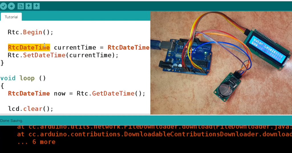
4. Upload the Arduino Code
Write or download the Arduino code for your digital clock. The code should include functions to set and read the time from the DS1307 RTC module, as well as display the time on the 16×2 LCD display. Test the code to ensure your clock displays the current time accurately.
5. Power Up Your Clock
Connect your Arduino to a power source, and your digital clock should come to life. The time should be displayed on the LCD, and it will continue to keep time accurate even after power cycles, thanks to the DS1307 RTC module.
Experiment and Expand
Once you’ve successfully created your Arduino digital clock, you can experiment and expand on your project.
Here are a few ideas to get you started:
- Add buttons or a rotary encoder to set the time and alarm;
- Incorporate an alarm feature to trigger a buzzer or LED at a specific time;
- Enhance the display by including date, temperature, or humidity readings;
- Experiment with different types of displays, such as OLED screens for a more modern look;
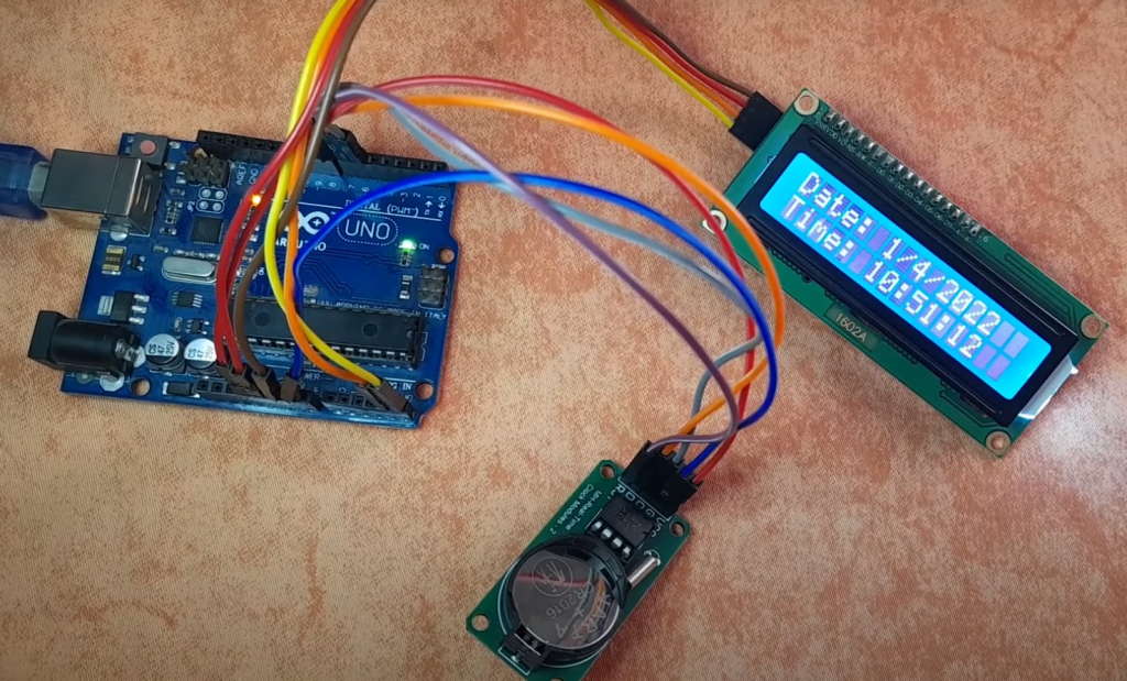
Arduino Digital Clock With DS1307 RTC Module:
Circuit Diagram
Before we dive into the nitty-gritty details of constructing our Arduino digital clock, let’s take a look at the essential component of our project – the circuit diagram. Understanding the connections and components involved is crucial for a successful build.
Components Required
To build our Arduino digital clock with the DS1307 RTC module, you will need the following components:
- Arduino Board (e.g., Arduino Uno): The heart of our project, the Arduino board will handle the clock’s control logic and display functions;
- DS1307 RTC Module: This module, based on the DS1307 RTC chip, provides highly accurate timekeeping functions. It communicates with the Arduino via the I2C protocol;
- 16×2 LCD Display: The liquid crystal display (LCD) will serve as the visual output for our digital clock, showing the time in a clear format;
- Potentiometer: To adjust the contrast and brightness of the LCD display, we’ll use a potentiometer;
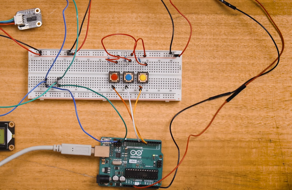
- Push Buttons: These buttons will allow us to set and adjust the time and date on our digital clock;
- Resistors: A few resistors for current limiting may be required depending on your specific LCD module;
- Connecting Wires: To establish connections between the various components and the Arduino;
- PCB Board (Optional): While not mandatory, designing a custom PCB can enhance the project’s aesthetics and durability [4];
With these components in hand, we can now proceed to connect them and bring our Arduino digital clock to life.
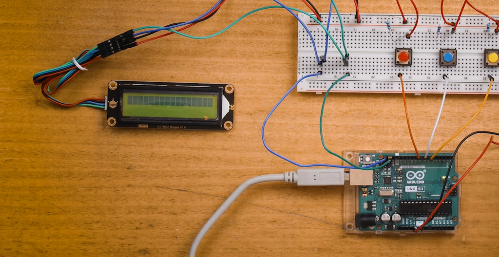
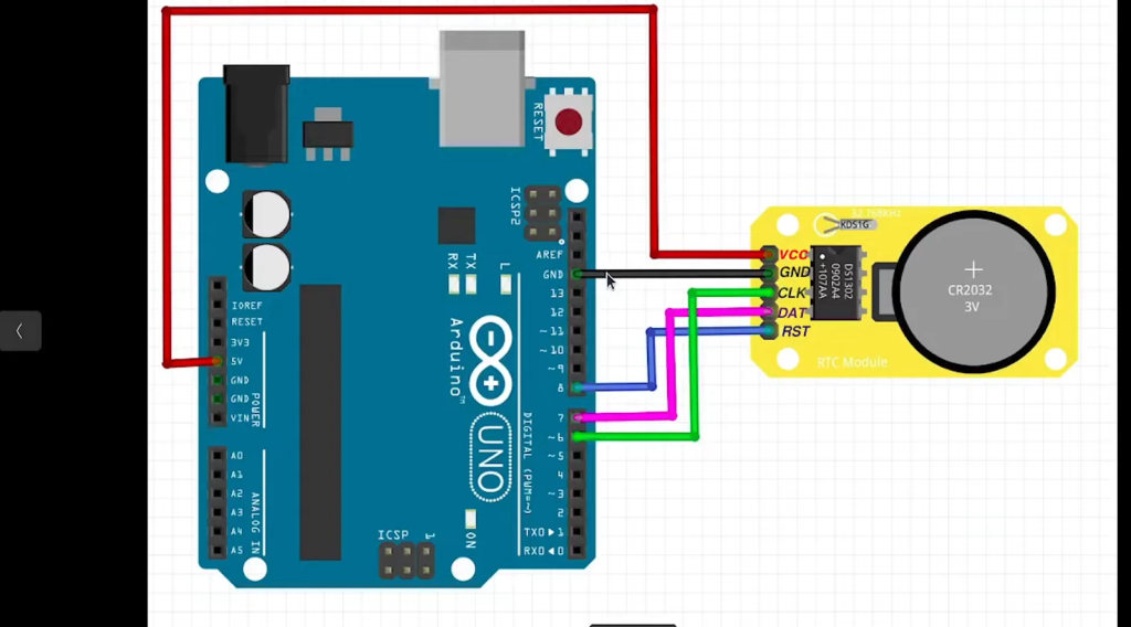
Circuit Connection of Arduino Digital Clock With DS1307 RTC Module
The success of our digital clock project hinges on correct circuit connections. Follow the steps below to ensure everything is wired up properly:
1. Arduino and DS1307 RTC Module Connections:
- Connect the VCC (5V) and GND pins on the DS1307 module to the 5V and GND pins on the Arduino, respectively;
- Wire the SDA (Serial Data) pin from the DS1307 module to Arduino’s A4 (analog pin 4);
- Connect the SCL (Serial Clock) pin from the DS1307 module to Arduino’s A5 (analog pin 5);
- Make sure to add pull-up resistors (4.7kΩ) on both the SDA and SCL lines. Connect one end of each resistor to the respective SDA and SCL lines and connect the other ends to the 5V supply line;
2. LCD Display Connections:
- Connect the VCC (5V) and GND pins on the LCD display to the 5V and GND pins on the Arduino;
- Connect the RS (Register Select), RW (Read/Write), and E (Enable) pins on the LCD display to digital pins on the Arduino (e.g., RS to D8, RW to GND, E to D9);
- Connect the D4, D5, D6, and D7 pins on the LCD display to digital pins on the Arduino (e.g., D4 to D4, D5 to D5, D6 to D6, D7 to D7);
- Adjust the LCD’s contrast using the potentiometer by connecting its two outer pins to VCC and GND and the middle pin to the Vo (contrast) pin on the LCD;
3. Push Button Connections:
- Connect one side of each push button to the GND pin on the Arduino;
- Connect the other side of each push button to separate digital pins on the Arduino (e.g., Set Time button to D2, Set Date button to D3, etc.);
With the circuit connections established, you have successfully set up the hardware for your Arduino digital clock with the DS1307 RTC module. The next step is to program the Arduino to control the clock’s functionality and display the time and date on the LCD.
Circuit Design Using PCB Software
1. Select PCB Design Software:
Choosing the right PCB design software is crucial. There are several popular options available, both free and paid, such as Eagle, KiCad, Fritzing, and Altium Designer. Select the one that suits your preferences and experience level.
2. Create a New Project:
Launch your chosen PCB design software and create a new project for your digital clock [5].
3. Import Components:
Begin by importing the components you plan to use in your digital clock project. Most PCB design software provides libraries with a wide range of components. Ensure that you have the footprints and symbols for the Arduino, DS1307 RTC module, LCD display, and push buttons.
4. Design the PCB Layout:
Now comes the fun part – designing the actual PCB layout. Start by placing the components on the virtual PCB board. Arrange them in a logical and compact manner to save space and ensure efficient routing:
- Position the Arduino board at the center of the PCB, allowing ample space for other components around it;
- Place the DS1307 RTC module close to the Arduino, considering the I2C communication lines;
- Position the LCD display so that it is easily readable and accessible;
- Arrange the push buttons in a user-friendly manner;
5. Route the Connections:
Connect the components by routing the traces on the PCB. Pay close attention to the following:
- Ensure that the power and ground connections are appropriately connected to all components;
- Route the I2C lines (SDA and SCL) from the DS1307 module to the Arduino;
- Connect the data pins from the LCD display to the Arduino;
- Establish connections between the push buttons and the Arduino;
6. Add Labels and Annotations:
Label all the components, connectors, and wires on the PCB layout to make it clear and understandable. Annotations and labels help prevent errors during the assembly process.
7. Check for Errors:
Before proceeding, run a design rule check (DRC) to identify any potential errors such as unconnected nets, overlapping components, or incorrect footprints.
8. Generate Gerber Files:
Once you are satisfied with the PCB layout and it passes the design rule check, generate the Gerber files. These files are essential for manufacturing the actual PCB.
9. Order the PCB:
Submit your Gerber files to a PCB fabrication service. Numerous online PCB manufacturers can produce your custom PCB design for a reasonable cost. Be sure to specify your requirements, such as PCB material, thickness, and quantity.
10. Solder Components:
When your custom PCBs arrive, it’s time to solder the components onto the board. Follow your PCB layout as a guide and take your time to ensure accurate soldering [6].
11. Test the Digital Clock:
Before finalizing your project, thoroughly test your newly assembled Arduino digital clock. Make sure it displays the time and date correctly, and that the push buttons function as expected.
Arduino Digital Clock Without RTC Module:
Components Required
To build this clock, you’ll need the following components:
- Arduino (e.g. Arduino Uno);
- 16×2 LCD Display;
- Push Buttons (for setting time);
- Breadboard and jumper wires;
- 10k Ohm Potentiometer (for adjusting LCD contrast);
- Resistor (10k Ohm);
- Capacitors (10uF);
- Crystal Oscillator (32.768 kHz);
- 2 x 22pF Capacitors;
- A few LEDs and resistors (for backlighting the LCD);
- Power source (9V adapter or battery);
Circuit Connection of Arduino Digital Clock Without RTC Module
Now that we have our components, let’s connect them according to the following circuit diagram:
- Connect the 16×2 LCD display to the Arduino following the pin configuration provided in the datasheet;
- Wire up the push buttons to the Arduino for setting the hours and minutes;
- Connect the 10k Ohm potentiometer to the LCD for adjusting contrast;
- Use the 10k Ohm resistor and capacitors to create the clock oscillator circuit;
- Add LEDs and resistors for backlighting the LCD;
- Power your Arduino with a 9V adapter or battery [7];
Make sure to double-check your connections and consult the datasheets of your components for detailed pinout information.
Circuit Design Using PCB Software
While you can initially build this digital clock on a breadboard for testing purposes, it’s advisable to design a custom PCB (Printed Circuit Board) for a more permanent and tidy solution. Using PCB design software like Eagle or KiCad, you can create a compact and organized layout for your components.
Here are some steps to get you started with PCB design:
- Start a new project in your chosen PCB design software;
- Import the components and draw the circuit connections;
- Arrange the components on the PCB layout;
- Route the traces to connect the components following your circuit diagram;
- Check for any errors or design rule violations;
- Once satisfied with your design, export it for manufacturing;
Manufacturing your PCB might involve sending the design files to a PCB manufacturer or using a DIY PCB etching method, depending on your preferences and resources.
Working Principle of Arduino Digital Clock Without RTC Module:
- Crystal Oscillator: The heart of our clock is a crystal oscillator with a 32.768 kHz frequency. This crystal oscillator provides a highly accurate time base for our clock;
- Arduino Microcontroller: The Arduino Uno serves as the brain of our clock. It reads the oscillations of the crystal oscillator and calculates the time based on these oscillations;
- LCD Display: The 16×2 LCD display shows the current time, allowing us to read it easily. The contrast of the LCD can be adjusted using the potentiometer;
- Push Buttons: We use push buttons to set the hours and minutes on our clock. These buttons allow us to interact with the Arduino and configure the time;
- Backlighting LEDs: LEDs provide backlighting for the LCD display, ensuring that the time is visible even in low-light conditions;
Here’s how the clock operates:
- The crystal oscillator generates precise oscillations at a rate of 32.768 kHz;
- The Arduino counts the number of oscillations to determine the time;
- The push buttons enable us to set the current time;
- The LCD display shows the hours and minutes;
This clock doesn’t rely on an RTC module’s battery backup, making it suitable for projects where a power source is readily available. However, it’s essential to note that the clock might lose track of time if the power is disconnected, as it doesn’t have a battery-powered backup [8].
Arduino Code
To make our Arduino digital clock function correctly, we need to upload the appropriate code to the Arduino Uno.
Below is a sample Arduino code that you can use as a starting point:
#include <LiquidCrystal.h>
LiquidCrystal lcd(12, 11, 5, 4, 3, 2);
int hours = 0;
int minutes = 0;
void setup() {
lcd.begin(16, 2);
pinMode(6, INPUT); // Button for setting hours
pinMode(7, INPUT); // Button for setting minutes
}
void loop() {
// Read buttons and update time if pressed
if (digitalRead(6) == HIGH) {
hours++;
if (hours > 23) {
hours = 0;
}
}
if (digitalRead(7) == HIGH) {
minutes++;
if (minutes > 59) {
minutes = 0;
}
}
// Display the time on the LCD
lcd.setCursor(0, 0);
lcd.print(“Time: “);
if (hours < 10) {
lcd.print(“0”);
}
lcd.print(hours);
lcd.print(“:”);
if (minutes < 10) {
lcd.print(“0”);
}
lcd.println(minutes);
delay(1000); // Update every second
}
This code initializes the LCD, reads the push buttons for setting hours and minutes, and continuously updates the LCD display with the current time.
Feel free to modify and expand upon this code to add additional features or customization to your digital clock [9].
FAQ:
1. How do I set the time on my Arduino RTC?
To set the time on an Arduino Real-Time Clock (RTC) module, you typically use a library like “DS3231” or “RTClib” if you’re using the DS3231 RTC module.
Here’s a general outline of the process:
- Connect the RTC module to your Arduino correctly;
- Include the appropriate RTC library in your Arduino sketch;
- Initialize the RTC object and set the time using functions provided by the library. For example, with the DS3231 library, you can use rtc.adjust(DateTime(year, month, day, hour, minute, second)); to set the time;
- Upload the sketch to your Arduino board;
- The RTC will now keep track of time even when the Arduino is powered off;
2. Does Arduino have a real-time clock library?
Yes, Arduino has several libraries for working with real-time clocks. The most commonly used ones are “DS3231” for the DS3231 RTC module and “RTClib” for various RTC modules. You can find these libraries in the Arduino Library Manager and easily include them in your projects [10].
3. How can I make an Arduino-based clock without an RTC module?
You can create a simple Arduino-based clock without an RTC module by using the Arduino’s internal clock (millis() or micros()) to keep track of time. However, this method won’t maintain time accurately if the Arduino is powered off or reset. To make a basic clock, you can increment a counter in your code and convert it to hours, minutes, and seconds for display.
4. Why is RTC used in Arduino digital clocks?
RTCs (Real-Time Clocks) are used in Arduino digital clocks because they provide accurate timekeeping even when the Arduino is powered off or reset. They maintain time independently of the Arduino’s microcontroller, ensuring that the clock remains accurate over time. This is crucial for applications like digital clocks where precise timekeeping is required.
5. How to create a clock in Arduino?
To create a clock in Arduino, you’ll need an RTC module for accurate timekeeping. Here are the general steps:
- Connect the RTC module to your Arduino;
- Include the appropriate RTC library;
- Initialize the RTC object and set the time;
- Continuously read the time from the RTC and display it on a display or serial monitor
- The exact code and components used will depend on your specific clock design;
6. Can I use an Arduino for a clock?
Yes, you can use an Arduino to create various types of clocks, such as digital clocks, analog clocks, and even more complex timekeeping devices. Arduino’s versatility makes it suitable for a wide range of clock projects.
7. How to make a digital clock with Arduino UNO?
Making a digital clock with an Arduino UNO involves connecting an RTC module, a display (e.g., LED matrix, LCD, or seven-segment display), and writing code to read the time from the RTC and display it on the chosen display.
8. How to make an LED clock with Arduino?
To make an LED clock with Arduino, you can use an array of LEDs to display hours, minutes, and seconds. You’ll need an RTC module to keep track of time accurately. Write code to update the LED display based on the time read from the RTC.
9. How accurate is the Arduino clock?
The accuracy of an Arduino’s internal clock (millis() or micros()) depends on the specific Arduino board and its crystal oscillator. It’s typically not as accurate as dedicated RTC modules. The drift can vary, but it might gain or lose a few seconds per day. RTC modules like the DS3231 are much more accurate, with deviations of just a few seconds per year.
10. How fast is the Arduino clock?
The speed of the Arduino clock depends on the specific model. For most Arduino boards, the clock speed is 16 MHz (16 million cycles per second). Some boards, like the Arduino Due, have a clock speed of 84 MHz. This clock speed determines the execution speed of your code and the accuracy of timing functions.
11. Does ATmega328 have a clock?
Yes, the ATmega328 microcontroller used in Arduino Uno and similar boards have an internal oscillator with a default clock frequency of 16 MHz. This clock is used to execute your Arduino code.
12. How to set clock frequency in Arduino?
You typically don’t change the clock frequency of the microcontroller on an Arduino board, as it’s set to a specific value (e.g., 16 MHz for most boards) by the manufacturer. Changing the clock frequency can affect the operation of the board and is not a common task in Arduino projects.
13. How to design a 24-hour digital clock?
To design a 24-hour digital clock with Arduino, follow the steps mentioned earlier for creating a clock. Ensure that your code correctly formats the time in a 24-hour format (0-23 hours) and displays it accordingly on your chosen display.
14. How many clocks are there in Arduino?
Arduino itself doesn’t have built-in clocks. Instead, Arduino can interface with various external components like RTC modules, which provide accurate timekeeping. The number of clocks you can use in Arduino depends on the hardware and libraries you choose for your specific project. Common RTC modules include the DS3231, DS1307, and PCF8523, among others.
Useful Video: Arduino Tutorial 35- Real Time Clock using DS1302 RTC Module
References:
- https://linuxhint.com/make-digital-clock-arduino-uno/
- https://www.instructables.com/How-to-make-a-Arduino-Digital-Clock/
- https://srituhobby.com/how-to-make-an-arduino-clock-step-by-step-complete-tutorial/
- https://maker.pro/arduino/projects/arduino-alarm-clock-using-real-time-clock-lcd-screen
- https://www.electronicsforu.com/electronics-projects/hardware-diy/arduino-real-time-digital-clock
- https://www.flyrobo.in/blog/real-time-clock-arduino
- https://www.circuitbasics.com/how-to-use-a-real-time-clock-module-with-the-arduino/
- https://circuitdiagrams.in/arduino-digital-clock/
- https://circuitdigest.com/microcontroller-projects/arduino-alarm-clock
- https://duino4projects.com/make-a-digital-clock-from-scratch-using-arduino/