
The Global Positioning System (GPS) is a vital technology that has significantly improved navigation and tracking systems worldwide. This article serves as a comprehensive guide for those interested in integrating GPS technology into their Arduino projects. It provides step-by-step instructions, from connecting the hardware components to writing and uploading the necessary code.
Whether you are a hobbyist or a professional developer, this guide offers valuable insights into the setup process, ensuring you can successfully harness the power of GPS technology in your Arduino applications
About GPS
GPS works in any weather conditions, anywhere in the world, 24 hours a day, with no subscription fees or setup charges. The U.S. Department of Defense continues to maintain the system and make improvements to it.
The GPS satellites circle the earth twice a day in a precise orbit. Each satellite transmits a unique signal and orbital parameters that allow GPS devices to decode and compute the precise location of the satellite. GPS receivers use this information to calculate the user’s exact location.
How Does GPS Work?
The Global Positioning System (GPS) works by using a method called “trilateration” which involves the use of at least three GPS satellites to accurately determine your location.
Here’s a step-by-step explanation:
- Satellite Signal Transmission: Each of the 24-plus satellites in the GPS network orbits the Earth twice a day, transmitting signals back to the planet. These signals, which travel at light speed, carry time-stamped information about the satellite’s location;
- Signal Reception by GPS Device: Your GPS receiver, which could be a standalone device or integrated into your smartphone or car, listens for the signals being sent by these satellites. It’s important to note that a GPS receiver must be locked onto the signal of at least four satellites to effectively calculate its 3D position (latitude, longitude, and altitude);
- Time Delay Calculation: Once the signals are received, the GPS device calculates the distance between it and each of the satellites. This is done by figuring out how long it took for each satellite’s signal to reach the receiver. Since the signals travel at a known speed (the speed of light), the distance can be calculated by multiplying the speed of light by the time it took for the signal to reach the receiver;
- Trilateration: With the distance to at least three satellites known, the GPS receiver can now perform a process called trilateration. Simply put, it determines where these distances intersect, and that intersection point is your location;
- Displaying the Information: Once your location has been determined, the GPS unit can display this information on a map or use it to provide directions [2];
Remember, this entire process happens in real-time and updates constantly, which allows GPS to track movement and provide turn-by-turn navigation instructions.
How to Use the GPS on the Arduino?
Now that we have a basic understanding of how GPS technology functions let’s explore how you can use GPS with an Arduino. Arduino is an open-source electronics platform that allows you to create various projects, including GPS-based ones.
To get started with GPS on Arduino, follow these steps:
1. Get the Necessary Components
To use GPS with Arduino, you’ll need the following components:
- An Arduino board (e.g., Arduino Uno, Arduino Nano);
- A GPS module compatible with Arduino (e.g., the NEO-6M or the UBlox series);
- Jumper wires for connecting the GPS module to the Arduino;
- A power source for the Arduino and GPS module (e.g., a USB cable and power bank);
2. Wiring the GPS Module
Connect the GPS module to your Arduino following the module’s datasheet or pinout diagram. Typically, you’ll need to connect wires for power (VCC and GND), communication (TX and RX), and possibly a few other pins depending on the specific module.
3. Install the Necessary Libraries
To make working with GPS easier, you can install Arduino libraries that provide functions for parsing and processing GPS data. Popular libraries include “TinyGPS++” and “Adafruit GPS Library.” You can install these libraries using the Arduino IDE’s Library Manager.
4. Write Arduino Code
Now, it’s time to write your Arduino code. Your code will depend on your specific project goals, but it generally involves initializing the GPS module, reading and parsing GPS data, and using that data for your intended purpose [3].
Here’s a simplified example of code to get you started:
#include <TinyGPS++.h>
#include <SoftwareSerial.h>
TinyGPSPlus gps;
SoftwareSerial ss(10, 11); // RX, TX
void setup() {
Serial.begin(9600);
ss.begin(9600);
}
void loop() {
while (ss.available() > 0) {
if (gps.encode(ss.read())) {
if (gps.location.isUpdated()) {
Serial.print(“Latitude: “);
Serial.println(gps.location.lat(), 6);
Serial.print(“Longitude: “);
Serial.println(gps.location.lng(), 6);
Serial.print(“Altitude (meters): “);
Serial.println(gps.altitude.meters());
}
}
}
}
This code initializes the GPS module, reads GPS data from the module, and prints latitude, longitude, and altitude information to the Arduino’s serial monitor [4].
5. Upload and Test
Upload your Arduino code to the board and open the serial monitor in the Arduino IDE. You should see GPS data being printed if the module is receiving a signal. Take your setup outdoors with a clear view of the sky to get accurate GPS coordinates.
Information Types Contained in a GPS Signal
GPS signals contain various types of information that enable receivers to calculate their precise position:
1. Satellite Identifiers
Each satellite signal includes a unique identifier, allowing the GPS receiver to distinguish between signals from different satellites. These identifiers help the receiver calculate distances and positions accurately.
2. Ephemeris Data
The GPS signal contains ephemeris data, which provides detailed information about the satellite’s orbit, clock corrections, and other parameters. This data helps the receiver predict the satellite’s position with high accuracy.
3. Pseudorandom Noise (PRN) Codes
PRN codes are complex, pseudorandom sequences that modulate the GPS signals. They serve several purposes, including helping the receiver synchronize with the satellite’s signal, calculate time delays, and identify the satellite’s source of the signal.
4. Almanac Data
The GPS signal also contains an almanac, which is a broad overview of all the satellites in the constellation. This data helps the receiver identify which satellites are in view and which ones are likely to provide the strongest signals.
5. Navigation Message
The navigation message is a continuous stream of data that includes information about the GPS satellite’s health, status, and precise location in orbit. It also contains the current GPS time, which is crucial for accurate timekeeping and position calculations.
6. Time of Transmission
The GPS signal includes the time at which the signal was transmitted by the satellite. This time is known as GPS time and serves as a reference for calculating distances between the receiver and the satellites.
7. Carrier Frequency
GPS signals use two carrier frequencies: L1 and L2. These frequencies are used to measure the time it takes for the signal to travel from the satellite to the receiver. By comparing the phase of the carrier wave, the receiver can determine more accurate distances.
Interpreting GPS Module Data:
GPS Libraries
GPS libraries are collections of pre-written code that allow you to interface with GPS modules easily. They provide functions to parse the raw NMEA sentences transmitted by GPS modules, extract useful information, and make it accessible for further processing.
1. TinyGPS
TinyGPS is a lightweight GPS library designed for Arduino. It is known for its simplicity and ease of use, making it a great choice for beginners. TinyGPS can parse NMEA sentences and extract latitude, longitude, altitude, speed, and other essential GPS data.
2. TinyGPS++
TinyGPS++ is an improved version of the original TinyGPS library. It offers more advanced features and better performance. TinyGPS++ can handle NMEA sentences, and it provides an object-oriented approach to working with GPS data. It can parse not only basic location data but also more advanced information like course over ground, date, and time [5].
TinyGPS
Installation:
- Open the Arduino IDE;
- Go to “Sketch” > “Include Library” > “Manage Libraries…”;
- In the Library Manager, type “TinyGPS” in the search bar;
- Click the “Install” button next to “TinyGPS” to install the library;
Sample Code Using TinyGPS:
Here’s a simple example of how to use the TinyGPS library to interpret GPS module data:
#include <TinyGPS.h>
// Create a TinyGPS object
TinyGPS gps;
void setup() {
Serial.begin(9600);
Serial.println(“GPS Module Test”);
}
void loop() {
// Read characters from the GPS module
while (Serial.available()) {
char c = Serial.read();
// Feed the character to the TinyGPS library
gps.encode(c);
}
// Check if there is new GPS data available
if (gps.location.isUpdated()) {
Serial.print(“Latitude: “);
Serial.println(gps.location.lat(), 6); // Print latitude with 6 decimal places
Serial.print(“Longitude: “);
Serial.println(gps.location.lng(), 6); // Print longitude with 6 decimal places
Serial.print(“Altitude (meters): “);
Serial.println(gps.altitude.meters());
Serial.print(“Speed (km/h): “);
Serial.println(gps.speed.kmph());
Serial.println();
}
}
In this example:
- We include the TinyGPS library at the beginning;
- We create a TinyGPS object called “gps”;
- In the loop function, we continuously read characters from the GPS module through the serial connection;
- We feed each character to the TinyGPS object using gps.encode(c);
- We check if there is new GPS data available using gps.location.isUpdated();
- If new data is available, we print latitude, longitude, altitude, and speed;
This code provides a basic template for working with GPS data using the TinyGPS library. You can expand on it to suit your specific project requirements.
TinyGPS++
TinyGPS++ is an advanced GPS library that offers more features and improved performance compared to the original TinyGPS library. It follows an object-oriented approach, making it easier to work with GPS data.
Installation:
- Open the Arduino IDE;
- Go to “Sketch” > “Include Library” > “Manage Libraries…”;
- In the Library Manager, type “TinyGPS++” in the search bar;
- Click the “Install” button next to “TinyGPS++” to install the library;
Sample Code Using TinyGPS++:
Here’s a simple example of how to use the TinyGPS++ library to interpret GPS module data:
#include <TinyGPS++.h>
#include <SoftwareSerial.h>
TinyGPSPlus gps;
void setup() {
Serial.begin(9600);
Serial.println(“GPS Module Test”);
}
void loop() {
while (Serial.available()) {
gps.encode(Serial.read());
}
if (gps.location.isUpdated()) {
Serial.print(“Latitude: “);
Serial.println(gps.location.lat(), 6);
Serial.print(“Longitude: “);
Serial.println(gps.location.lng(), 6);
Serial.print(“Altitude (meters): “);
Serial.println(gps.altitude.meters());
Serial.print(“Speed (km/h): “);
Serial.println(gps.speed.kmph());
Serial.println();
}
}
This code is similar to the previous example using TinyGPS. However, it includes the TinyGPS++ library and defines a TinyGPSPlus object called “gps”. The rest of the code remains largely the same [6].
Both libraries make it easy to parse and extract GPS data, so you can focus on using that data for your specific applications, whether it’s for tracking, navigation, or any other creative project you have in mind.
Explaining GPS Module for Arduino Interfacing
Interfacing a GPS module with an Arduino involves connecting the GPS module to the Arduino board and writing code to communicate with and extract data from the module.
Components You’ll Need:
- Arduino Board: You can use various Arduino models like Arduino Uno, Arduino Nano, or Arduino Mega;
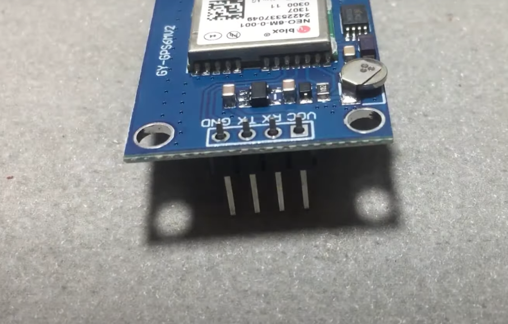
- GPS Module: Select a GPS module compatible with Arduino, such as the NEO-6M or UBlox series. These modules typically use the UART (serial) communication protocol;
- Jumper Wires: You’ll need jumper wires to establish the connections between the Arduino and GPS module
- Power Source: Depending on your specific GPS module, you may need an external power source to provide sufficient voltage and current;
Steps for Interfacing a GPS Module with an Arduino:
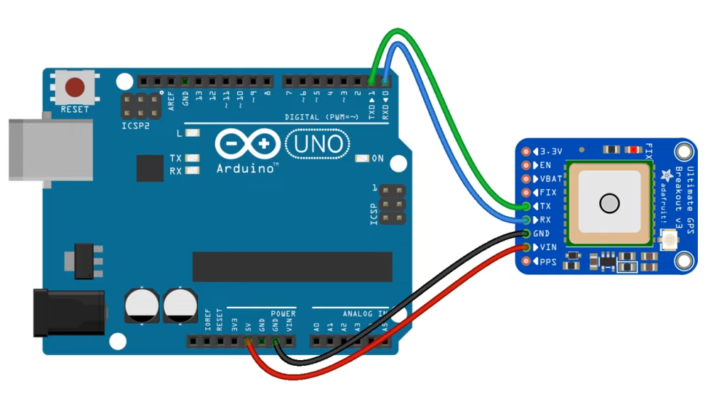
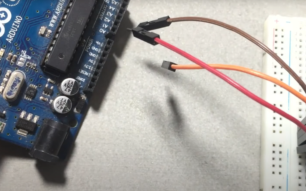
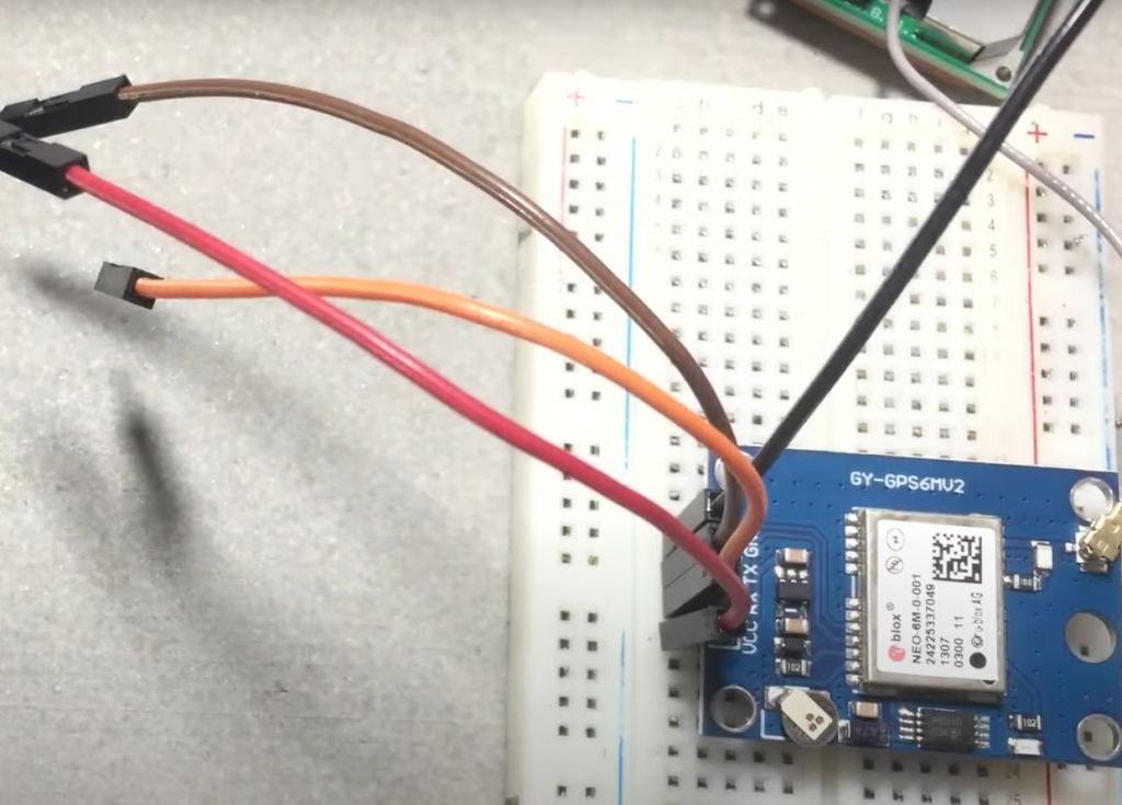
1) Connect the GPS Module to the Arduino:
- Power Connections: GPS modules usually require a 3.3V or 5V power supply. Connect the module’s VCC pin to the Arduino’s 3.3V or 5V output pin. Also, connect the GPS module’s GND pin to the Arduino’s GND pin;
- Serial Communication: GPS modules typically communicate with the Arduino via UART (serial) communication. Connect the TX (transmit) pin of the GPS module to the RX (receive) pin of the Arduino, and connect the RX (receive) pin of the GPS module to the TX (transmit) pin of the Arduino. This establishes a serial communication link between the GPS module and Arduino;
- Optional Connections: Depending on your GPS module, you might have additional pins for features like PPS (Pulse-Per-Second) output or enabling/disabling the module. Refer to your GPS module’s datasheet or documentation for guidance on these pins;
2) Install the Necessary Libraries:
To make interfacing with the GPS module easier, you can install Arduino libraries that provide functions for parsing and processing GPS data. Two commonly used libraries are “TinyGPS” and “TinyGPS++”. You can install these libraries using the Arduino IDE’s Library Manager [7].
3) Write Arduino Code:
You’ll need to write Arduino code to read and interpret the GPS data from the module.
Here’s a simplified example of Arduino code for reading GPS data using the TinyGPS library:
#include <TinyGPS.h>
// Create a TinyGPS object
TinyGPS gps;
void setup() {
Serial.begin(9600);
Serial.println(“GPS Module Test”);
}
void loop() {
// Read characters from the GPS module
while (Serial.available()) {
char c = Serial.read();
// Feed the character to the TinyGPS library
gps.encode(c);
}
// Check if there is new GPS data available
if (gps.location.isUpdated()) {
Serial.print(“Latitude: “);
Serial.println(gps.location.lat(), 6); // Print latitude with 6 decimal places
Serial.print(“Longitude: “);
Serial.println(gps.location.lng(), 6); // Print longitude with 6 decimal places
Serial.print(“Altitude (meters): “);
Serial.println(gps.altitude.meters());
Serial.print(“Speed (km/h): “);
Serial.println(gps.speed.kmph());
Serial.println();
}
}
This code initializes the GPS module, reads GPS data from the module’s serial communication, and prints latitude, longitude, altitude, and speed information to the Arduino’s serial monitor.

4) Upload and Test:
Upload your Arduino code to the board using the Arduino IDE and ensure that the serial monitor is open. When the GPS module receives signals from satellites, the code will interpret and display the relevant GPS data on the serial monitor. Take your setup outdoors with a clear view of the sky to receive GPS signals and get accurate location data [8].
Interfacing GPS Module With Arduino:
About UBlox NEO-M8N GPS Module
Interface GPS Module With Arduino Uno
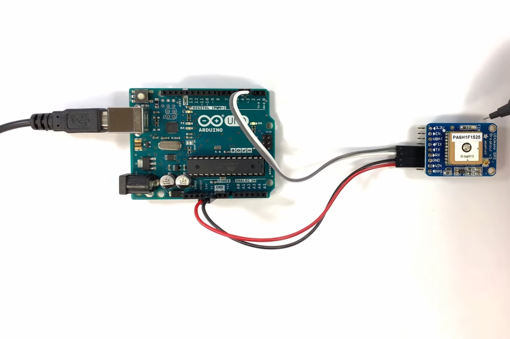
To interface the UBlox NEO-M8N GPS module with Arduino Uno, you’ll need a few things:
- UBlox NEO-M8N GPS Module;
- Arduino Uno;
- Connecting wires;
- Breadboard;
Here are the steps:
- Connect the VCC pin of the GPS module to the 5V pin on the Arduino;
- Connect the GND pin of the GPS module to the GND pin on the Arduino;
- Connect the RX pin of the GPS module to the TX pin on the Arduino;
- Connect the TX pin of the GPS module to the RX pin on the Arduino;
Connect Arduino With PC
Once you have connected the Arduino Uno with the GPS module, it’s time to connect the Arduino to your computer. Use the USB cable to connect the Arduino Uno to your PC. Make sure the drivers for your Arduino Uno are installed on your computer.
Download Libraries and Install
To make the GPS module work with the Arduino, you will need to download and install the “TinyGPS++” library. This library simplifies the task of interfacing the GPS module with Arduino. You can download it from the Arduino IDE by navigating to Sketch -> Include Library -> Manage Libraries, then search for “TinyGPS++” and click on Install.
Arduino Software (IDE)
The Arduino Integrated Development Environment (IDE) is a software application that allows you to write and upload code to the Arduino board. It’s user-friendly and available for Windows, Mac OS X, and Linux. Once you’ve installed the Arduino IDE and the necessary libraries, it’s time to write the code.
Create An Output
To create an output, you’ll need to write a program that reads data from the GPS module and outputs it to the Serial Monitor. Here’s a simple example:
#include <TinyGPS++.h>
TinyGPSPlus gps;
void setup()
{
Serial.begin(9600);
}
void loop()
{
while (Serial.available() > 0)
if (gps.encode(Serial.read()))
displayInfo();
if (millis() > 5000 && gps.charsProcessed() < 10)
{
Serial.println(“No GPS detected”);
while(true);
}
}
void displayInfo()
{
if (gps.location.isValid())
{
Serial.print(“Latitude: “);
Serial.println(gps.location.lat(), 6);
Serial.print(“Longitude: “);
Serial.println(gps.location.lng(), 6);
}
else
{
Serial.println(“Location: Not Available”);
}
}
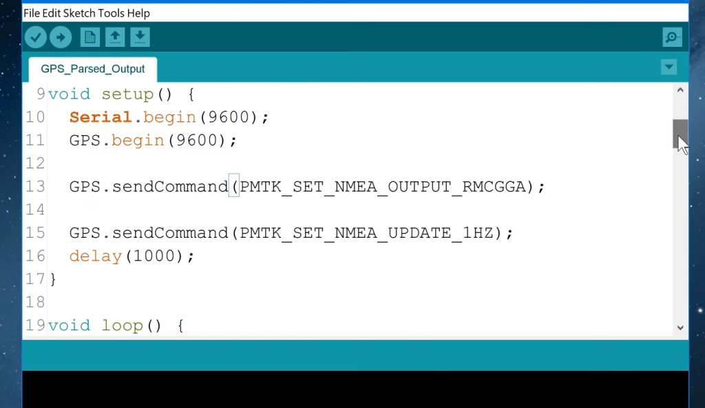
Decoding the NMEA Message Structure
The data sent by the GPS module is in the form of NMEA sentences. NMEA stands for National Marine Electronics Association, which created this standard for data communication in marine applications. Each sentence starts with a ‘$’ sign, followed by a five-character identifier (e.g., “GPGGA” for Global Positioning System Fix Data), and then comma-separated data fields.
The TinyGPS++ library simplifies the task of decoding NMEA sentences. It automatically parses the incoming data, checks it for validity, and makes the data available in easy-to-use variables.

FAQ:
1. Why should you use the U-BLOX Neo-6M GPS module on Arduino?
The U-BLOX Neo-6M GPS module is a popular choice for use with Arduino due to several advantages:
- High Accuracy: The Neo-6M module offers good accuracy for its price range, making it suitable for various Arduino projects that require location data;
- Ease of Use: It is relatively easy to interface with Arduino using UART communication. Arduino libraries such as TinyGPS or TinyGPS++ simplify data parsing;
- NMEA Support: The Neo-6M module provides NMEA (National Marine Electronics Association) data output, which is a standardized format for GPS data. This makes it compatible with a wide range of Arduino libraries;
- Affordability: The Neo-6M is cost-effective, making it an attractive option for hobbyists and makers;
- Reliability: U-BLOX is a reputable manufacturer known for producing reliable and accurate GPS modules;
2. What signal does an Arduino code generate?
Arduino code generates electrical signals in the form of voltage levels or pulses to control various components and perform tasks. These signals can be digital (binary) or analog (varying voltage levels).
The specific signals generated by Arduino code depend on the instructions within the code and the connected hardware. For example:
- Digital Signals: Arduino code can generate digital signals that are either HIGH (5 volts) or LOW (0 volts) to turn LEDs on and off, control motors, read switches, and communicate with other digital devices;
- Analog Signals: Arduino can generate analog signals by using PWM (Pulse Width Modulation) to create varying voltage levels. This is commonly used for controlling the speed of motors, dimming LEDs, or generating audio tones;
- Serial Signals: Arduino can send and receive serial data, which consists of a series of voltage level changes representing binary data. This is used for communication with other devices, including GPS modules;
3. How to test GPS with Arduino?
To test a GPS module with an Arduino, follow these steps:
- Hardware Connections: Connect the GPS module to the Arduino as per the module’s datasheet or documentation. Ensure that you have proper power, ground, TX, and RX connections;
- Upload Code: Write or upload Arduino code to read GPS data from the module. You can use libraries like TinyGPS or TinyGPS++ to parse GPS data. The code should print GPS information to the Arduino’s serial monitor;
- Power On: Power up the Arduino and the GPS module. Ensure that the GPS module has a clear view of the sky for satellite reception;
- Serial Monitor: Open the Arduino IDE and go to “Tools” > “Serial Monitor” to view the output. You should see GPS data displayed, including latitude, longitude, altitude, and other relevant information;
- Outdoor Testing: For accurate GPS data, take the setup outdoors or place it near a window with an unobstructed view of the sky. GPS modules require a clear line of sight to the satellites;
- Wait for a Fix: It may take a few minutes for the GPS module to acquire a satellite fix, especially if it’s the first time you’re using it or if you’ve moved to a new location
- Data Verification: Verify that the GPS data displayed on the serial monitor is accurate and corresponds to your location;
4. How accurate is the Arduino GPS module?
The accuracy of an Arduino GPS module, such as the U-BLOX Neo-6M or similar models, can vary depending on several factors. Generally, these modules offer decent accuracy for many applications, but the level of precision may not be on par with specialized high-end GPS equipment.
Here are factors that can affect the accuracy of an Arduino GPS module:
- Number of Satellites: The more satellites the GPS module can “see,” the more accurate the position determination. Typically, a GPS module needs signals from at least four satellites to calculate latitude, longitude, altitude, and time accurately. In practical terms, having signals from more satellites improves accuracy;
- Signal Strength: The strength of the GPS signals received by the module can impact accuracy. Weak signals, due to obstructions or interference, may lead to less accurate readings;
- Signal Multipath: Signal multipath occurs when GPS signals bounce off nearby surfaces (e.g., buildings, trees) before reaching the module’s antenna. This can introduce errors in positioning;
- Dilution of Precision (DOP): DOP values, such as HDOP (Horizontal Dilution of Precision) and VDOP (Vertical Dilution of Precision), provide information about the geometric configuration of satellites in view. Lower DOP values correspond to higher accuracy;
- Satellite Ephemeris Data: The quality of the ephemeris data received from satellites can affect accuracy. Ephemeris data includes information about the satellites’ orbits, which is crucial for precise positioning;
- Module Quality: The quality and sensitivity of the GPS module itself play a role in accuracy. Higher-end GPS modules may provide better accuracy than lower-cost options;
- Environment: Environmental conditions, such as atmospheric disturbances and multipath interference, can impact accuracy. Outdoor, open-sky conditions generally yield better accuracy than indoor or obstructed environments;
In typical scenarios, a good-quality Arduino GPS module can provide accuracy within a few meters (2-10 meters) horizontally and a few meters vertically. However, for applications requiring extremely high accuracy, such as surveying or geodesy, specialized GPS equipment with post-processing may be necessary.
5. Is GPS free to use?
Yes, GPS (Global Positioning System) is free to use for civilian and commercial purposes. The U.S. government, which operates the GPS system, provides access to the GPS satellite signals worldwide at no cost. This policy of open and free access to GPS signals has been in place since the 1990s.
While GPS itself is free, there are some key points to note:
- Receivers: Users need GPS receivers, such as GPS modules or GPS-enabled devices (e.g., smartphones), to receive and interpret GPS signals. These receivers may vary in price and capabilities;
- Accuracy Augmentation Services: Some organizations and agencies provide augmentation services to enhance the accuracy of GPS positioning. Examples include the Wide Area Augmentation System (WAAS) in the United States and the European Geostationary Navigation Overlay Service (EGNOS) in Europe. While these services are often available for free, they may require compatible GPS receivers;
- Data Usage: While GPS itself does not require internet access, some GPS applications may use internet connectivity to enhance functionality. For example, mapping and navigation apps on smartphones may use internet data to download maps and provide real-time traffic updates;
6. Does the GSM module have GPS?
A GSM (Global System for Mobile Communications) module is primarily designed for mobile communication, such as sending and receiving SMS messages or connecting to the internet via cellular networks. However, not all GSM modules have integrated GPS functionality.
If a GSM module has integrated GPS capabilities, it is referred to as a “GSM/GPS module” or “GSM/GNSS module” (GNSS stands for Global Navigation Satellite System, which includes GPS). These combined modules provide both GSM communication and GPS positioning in a single device.
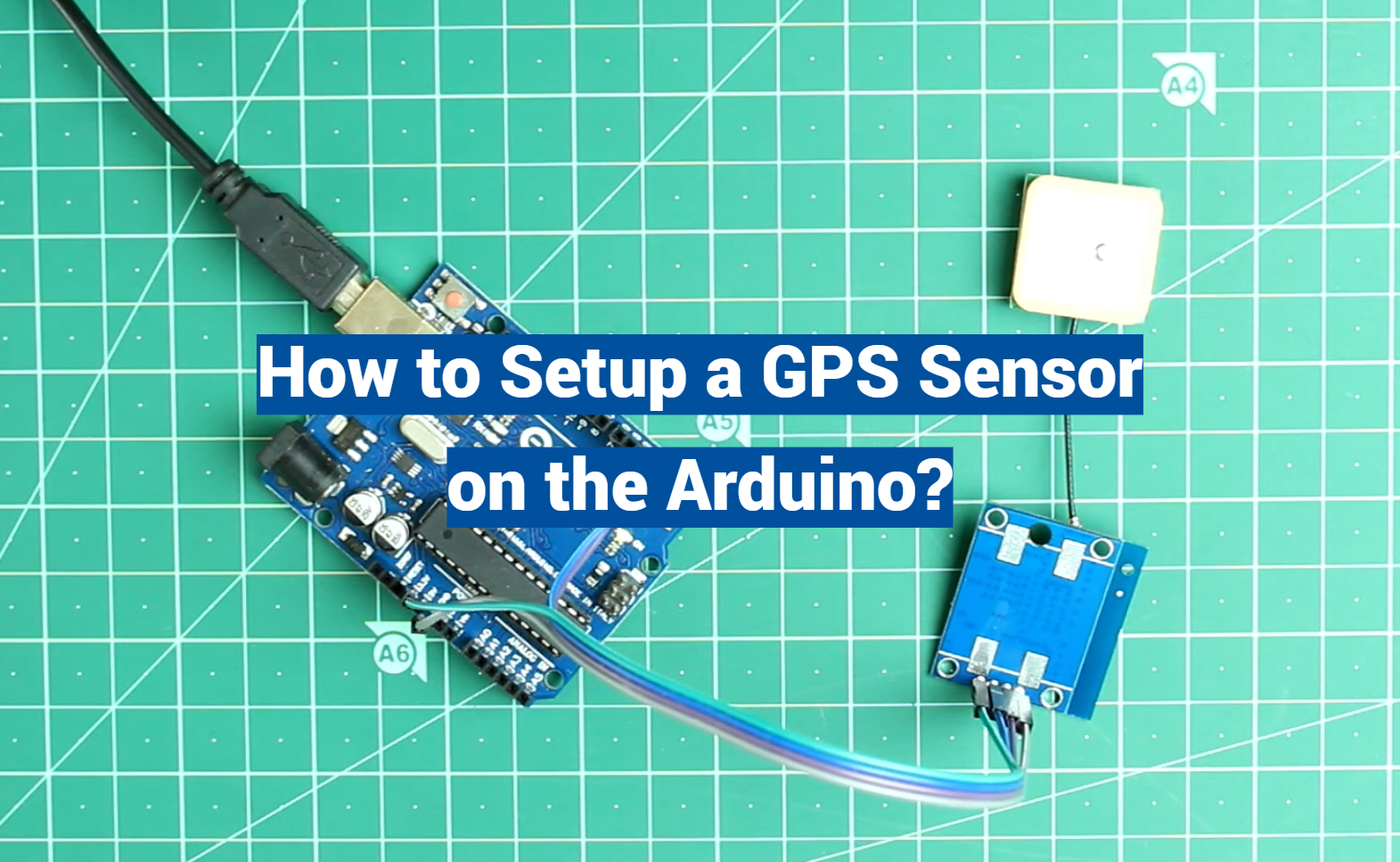
Useful Video: How to a Set Up a GPS Sensor on the Arduino – Ultimate Guide to the Arduino #45
References:
- https://www.circuitbasics.com/how-to-setup-a-gps-sensor-on-the-arduino/
- https://www.arrow.com/en/research-and-events/articles/hands-on-with-arduino-gps-usage
- https://www.instructables.com/Interfacing-GPS-Module-With-Arduino-Uno/
- https://circuitdigest.com/microcontroller-projects/reading-gps-data-using-computer-and-arduino
- https://dronebotworkshop.com/using-gps-modules/
- https://medium.com/@manindgera12/creating-a-gps-tracking-device-using-an-arduino-67d7868f046f
- https://makersportal.com/blog/2019/9/4/arduino-gps-tracker
- https://www.raypcb.com/gps-module-for-arduino-interfacing/