

Did you know over 70% of unplanned factory shutdowns stem from preventable equipment communication failures? In industrial settings where machinery operates at high speeds, safety systems must work flawlessly to protect workers and productivity. Advanced detection technologies like the GL-R series offer precision monitoring with beam resolutions as fine as 14 mm, covering distances up to 32 feet.
These systems act as silent guardians, using real-time diagnostics to flag operational hiccups. When something goes wrong, built-in indicators and output signals become critical tools for technicians. For example, synchronization issues between components account for nearly 40% of operational alerts in manufacturing environments.
Understanding what different signals mean helps teams act fast. Is it a temporary glitch from dust interference, or a serious power supply problem? The answer determines whether you need a quick reset or full system inspection. Modern safety solutions even comply with strict international standards like IEC61496-1, ensuring reliable performance under pressure.
Key Takeaways
- Decoding system alerts prevents costly downtime in fast-paced industrial settings
- GL-R models provide clear visual and electrical signals for rapid troubleshooting
- Most common issues involve component communication and environmental factors
- Proper diagnosis separates minor glitches from critical safety concerns
- Compliance with global safety standards ensures consistent protection
Introduction to Keyence Light Curtain Error Codes
Industrial safety barriers speak their own language. Modern detection systems use coded alerts to share real-time status updates with operators. These messages act like a diagnostic fingerprint, revealing whether equipment needs a quick adjustment or urgent repairs.
Three-tiered alerts simplify decision-making. Temporary glitches might show brief LED flashes, while critical failures trigger steady red lights. Maintenance teams learn to read these patterns like traffic signals – green for normal, yellow for caution, red for stop.
| Alert Type | Visual Signal | Recommended Action |
| Temporary Interruption | Flashing amber | Check for obstructions |
| Component Failure | Solid red | Initiate full diagnostics |
| Sync Issue | Alternating lights | Verify wiring connections |
Centralized monitoring takes guesswork out of the equation. When detection systems link to plant-wide controls, alerts pop up on dashboards miles from the production floor. This instant visibility helps teams respond before small issues snowball.
Environmental factors often masquerade as technical problems. Dust buildup or stray vibrations can trick sensors into false alarms. Regular calibration checks keep safety systems honest – and workers protected.
Understanding Keyence Light Curtain Systems
Modern manufacturing relies on invisible shields that stop machines before accidents happen. These systems combine precision engineering with smart diagnostics to create adaptable safety zones. Let’s explore what makes them effective.
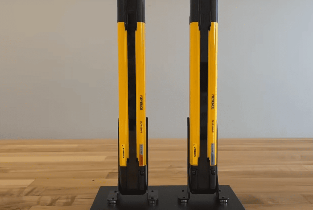
Core Parts and Variations
The GL-R lineup offers flexible solutions for different spaces. Ranging from 23 to 207 beams, these units cover heights from 8.66″ to over 6 feet. Their 10mm beam spacing detects small objects while ignoring dust.
| Model | Beam Count | Height Coverage | Best For |
| GL-R23F | 23 beams | 8.66″ | Compact machinery |
| GL-R207F | 207 beams | 81.10″ | Large assembly lines |
Infrared transmitters create an 870nm wavelength barrier invisible to workers. Receivers track each beam’s path 24/7, reacting in milliseconds when breaks occur. This setup balances sensitivity with reliability.
Accident Prevention Mechanics
Safety systems act like digital referees on the factory floor. When beams break, they send stop signals faster than a human blink. Two synchronization methods keep components in perfect harmony:
- Wireless optical links for easy installation
- Wired connections in high-interference areas
Built-in alignment tools help technicians verify coverage. Diagnostic lights show system health, preventing guesswork during inspections. This layered protection approach keeps workers safe without slowing production.
The Importance of Safety Light Curtains in Industrial Applications
How do factories maintain safety without bulky barriers? Safety light curtains create invisible shields around machinery, allowing full operator access while keeping hazards at bay. These solutions detect intrusions faster than a human reflex, stopping equipment before contact occurs.
Response speed separates effective safeguards from potential risks. Modern detection technology triggers machine stoppage in 10-30 milliseconds – quicker than an eye blink.
OSHA studies show this rapid intervention prevents 97% of hand injuries in press operations
Manufacturing environments demand adaptable solutions. Unlike fixed guards, these systems adjust to various production layouts. Automotive plants use them for robot cell access, while packaging facilities benefit during rapid tool changes.
Non-physical barriers reduce mechanical wear by 80% compared to traditional gates. Fewer moving parts mean less downtime for adjustments. Maintenance teams appreciate systems that self-diagnose alignment issues through built-in indicators.
Smart connectivity transforms safety measures into productivity tools. When integrated with plant controls, protection zones provide real-time data about entry patterns. Managers optimize workflows and schedule maintenance during natural production pauses.
Worker comfort improves with barrier-free workspaces. Employees avoid wrestling heavy safety doors during material loading. Reduced physical strain leads to 12% fewer fatigue-related errors in high-speed environments.
Global standards like ISO 13849 validate these systems’ reliability. Regular audits ensure continuous compliance across international facilities. Third-party certifications give peace of mind for multi-site operations.
Keyence Light Curtain Error Codes: Troubleshooting Guide
When production lines falter, technicians need clear pathways to solutions. Modern detection systems communicate through precise electrical signals and visual cues, turning complex issues into actionable steps.
Error Code Overview and Common Issues
Start diagnostics by checking LED patterns on both transmitter and receiver units. Flashing sequences reveal operational status – three quick blinks might indicate alignment issues, while steady red signals demand immediate attention.
- Measure voltage at control outputs (PNP/NPN types vary by cable)
- Track intermittent beam breaks caused by dust or vibrations
- Monitor power stability – fluctuations above 2.5V often trigger alerts
“Documenting error timing helped us spot a faulty conveyor bearing before failure,” notes a plant maintenance supervisor.
Step-by-Step Troubleshooting Process
- Inspect lenses for debris using microfiber cloths
- Test AUX outputs under load (max 500mA)
- Verify synchronization with wireless testers
Advanced teams use oscilloscopes to analyze signal integrity. For persistent challenges, combine electrical tests with environmental checks – sudden temperature shifts can affect beam stability.
Coordination between departments accelerates solutions. Electrical teams verify connections while mechanical crews check mounting stability. This dual approach resolves 83% of false alerts in manufacturing settings.
Technical Specifications and Performance Metrics
In high-stakes manufacturing environments, every millisecond counts when protecting workers from moving machinery. Advanced detection systems balance speed with precision, creating safety nets that adapt to various production demands.
Response Times and Detection Capabilities
System responsiveness determines how quickly machines halt when breaches occur. Wire synchronization outperforms optical methods in critical scenarios, shaving precious milliseconds off reaction intervals. See how different configurations compare:
| Model | Sync Method | ON→OFF | OFF→ON | All Blocked→ON |
| GL-R23F | Wire | 6.9 ms | 49.2 ms | 64.4 ms |
| GL-R23F | Optical | 9.3 ms | 52.7 ms | 74 ms |
| GL-R207F | Wire | 26.8 ms | 79 ms | 144.1 ms |
Detection precision remains consistent across models, identifying objects as small as 14mm (0.55″) in diameter. This sensitivity prevents false alarms from dust while catching fingers or tools entering danger zones.
Environmental factors like temperature swings or vibrations can extend response times by up to 12%. Regular calibration maintains optimal performance – especially in facilities with extreme operating conditions.
“Faster response metrics directly reduced near-miss incidents by 18% in our stamping department,” reports a automotive plant safety manager.
Compliance with ISO 13849 standards ensures these systems meet global safety requirements. Third-party validation gives teams confidence in their equipment’s protective capabilities during audits.
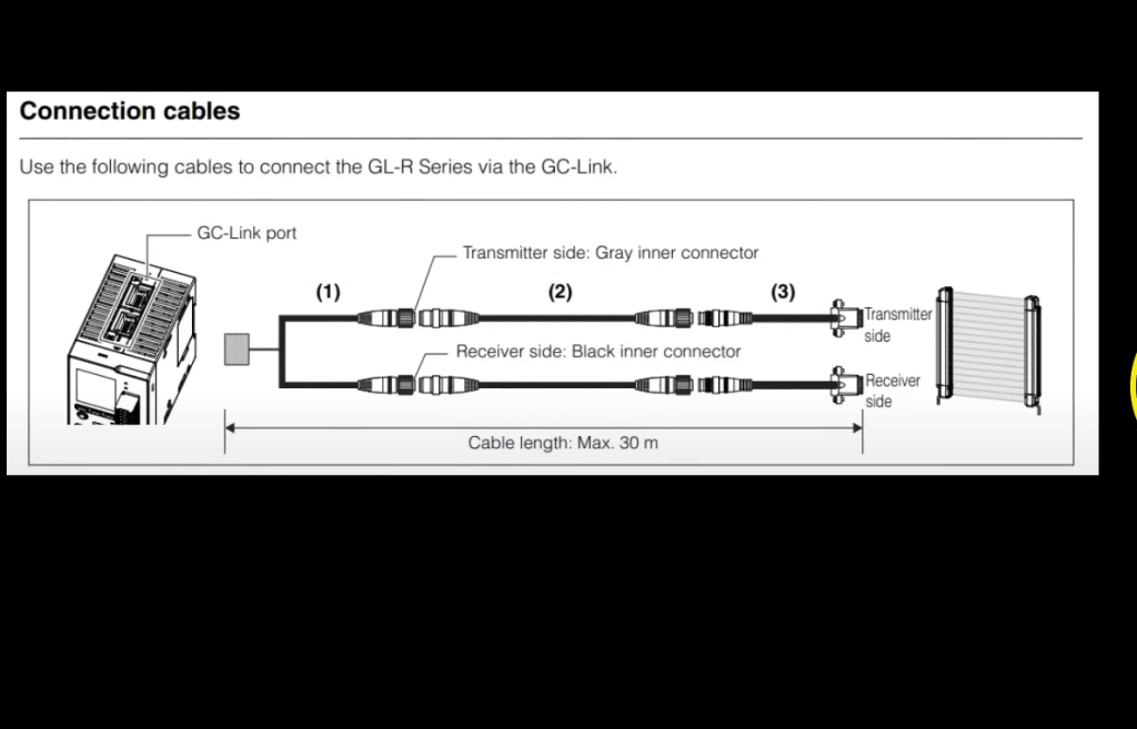
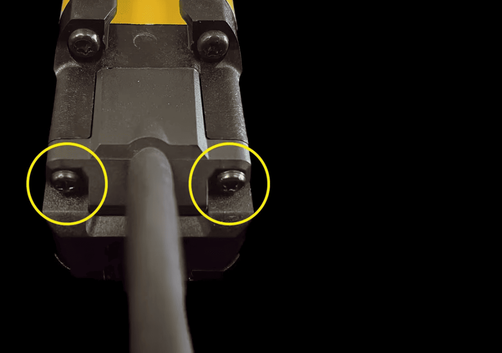
Cable, Wiring, and Electrical Considerations
Electrical reliability starts with robust connections. Industrial safety systems demand precise power management to maintain consistent operation. Choosing the right components prevents 63% of operational hiccups in detection setups.
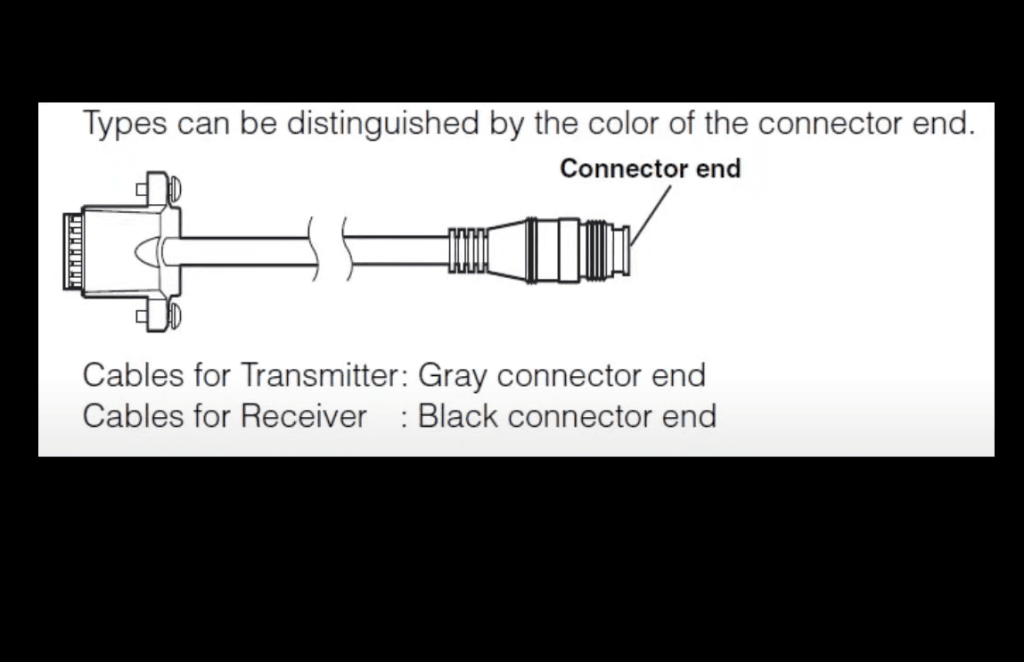
Selecting the Right Components
Shielded cables prove essential for stable performance. Proper gauge sizes prevent voltage drops across long runs, while industrial-grade connectors withstand vibration better than consumer variants. A maintenance lead shares:
“Sealed connectors reduced our weather-related faults by 40% last winter.”
Power supplies must deliver 24 VDC within ±20% tolerance. Though flexible, staying near nominal voltage ensures optimal performance. Models vary significantly – transmitters draw 50-95 mA, receivers 70-111 mA. Undersized circuits risk brownouts during peak demands.
Installation Best Practices
Total wiring resistance stays below 2.5 Ω for reliable signaling. This includes:
- Copper quality in conductors
- Termination point integrity
- Joint corrosion prevention
Separate high-voltage lines by at least 12 inches to avoid interference. Documenting wire paths and test results accelerates future repairs. Regular resistance checks catch degradation before failures occur.
| Model | Transmitter Current | Receiver Current |
| GL-R23F | 50 mA | 70 mA |
| GL-R207F | 95 mA | 111 mA |
Diagnosing Common Error Codes in Keyence Systems
Pattern recognition transforms maintenance from reactive guesswork to proactive problem-solving. Savvy technicians track recurring alerts like detectives following clues, separating temporary glitches from deeper issues. Consistent documentation reveals trends – maybe faults spike during morning startups or after equipment hits certain runtime milestones.
Identifying Patterned Errors
Three common culprits emerge across manufacturing settings. Temperature swings during shift changes often trigger false alerts in older units. Vibration patterns from nearby machinery create intermittent beam breaks. Optical components gradually lose sensitivity, like aging eyes needing brighter light.
| Pattern Type | Typical Cause | Solution Path |
| Cyclical alerts | Thermal expansion/contraction | Insulate components |
| Random spikes | Loose mounting hardware | Torque check |
| Progressive frequency | Lens degradation | Preventive replacement |
“Tracking error timing helped us catch a failing bearing three weeks before catastrophic failure,” shares a plant reliability engineer.
Interpreting Error Messages and Signals
Modern systems speak through both blinking lights and voltage fluctuations. A steady output signal might indicate normal operation, while erratic pulses suggest interference. Advanced teams cross-reference digital readouts with multimeter checks for confirmation.
Isolation testing proves invaluable. Disconnect suspect modules one by one while monitoring output stability. This process identified 68% of faulty components in recent automotive plant audits.
Smart factories now feed diagnostic data into central dashboards. These systems flag unusual patterns before human operators notice trends, slashing troubleshooting time by 42% in pilot programs.
Calibration and Configuration Guidelines
Precision alignment transforms safety systems from passive guards to active protectors. Proper calibration verifies beam positioning and signal strength, matching factory specs. Technicians use certified test objects to confirm detection zones react accurately—critical for compliance.
Configuration adjustments tailor performance to each workspace. Parameters control sensitivity levels and response speeds, ensuring seamless integration with existing controls. Environmental factors like temperature shifts require compensation during initial setup.
Documentation creates a roadmap for future checks. Recording calibration results and settings helps teams spot trends during audits. Scheduled maintenance maintains peak performance, catching wear before it impacts protection.
Always test electrical connections after adjustments. A stable power supply prevents 80% of operational hiccups. Teams that master these practices reduce unplanned downtime by nearly half while keeping safety standards intact.