Did you know that the tiny sensor in your smartphone that lets you play games by tilting the screen is part of a multi-billion dollar industry? This technology, based on Micro Electro Mechanical Systems (MEMS), is the same foundation that powers advanced motion tracking.
Welcome to your complete guide on harnessing this power. We will explore a popular 9-axis IMU, or Inertial Measurement Unit. This powerful sensor combines a gyroscope, accelerometer, and magnetometer into one compact module.
This integration makes it a top choice for creators today. It offers exceptional precision for measuring acceleration, rotation, and magnetic fields all at once. Whether you are building a drone or a motion-controlled gadget, this component provides the reliability you need.
This guide will walk you through the entire process. You will learn the technical basics, see wiring diagrams, and get practical code examples. We will cover setup, calibration, and exciting real-world applications.
By the end, you will have the confidence to incorporate this versatile sensor into your own projects. You will unlock new possibilities for interactive devices and sophisticated motion tracking.
Key Takeaways
- The MPU9250 is a 9-degree-of-freedom (9-DOF) sensor that combines three different motion-sensing technologies.
- It uses MEMS architecture, the same technology found in many modern consumer electronics.
- This IMU communicates with microcontrollers like Arduino using the common I2C protocol.
- Its ability to track multiple types of movement simultaneously makes it ideal for complex projects.
- Learning to use this sensor opens doors to creating drones, navigation systems, and interactive devices.
- Proper calibration is essential for obtaining accurate and reliable data from the unit.
Introduction to the MPU9250 Sensor
Today’s advanced motion detection systems stem from decades of innovation in micro-scale engineering. This progress has produced remarkable components like the sophisticated 9-axis sensor we’ll explore here.
Overview and Key Features
The mpu9250 represents cutting-edge MEMS technology in a compact package. It combines three distinct measurement systems into one efficient module.
This imu operates on low voltage (2.4-3.6V) with minimal power consumption. Its 16-bit ADC delivers exceptional precision for all measurements.
| Sensor Type | Programmable Ranges | Units |
|---|---|---|
| Accelerometer | ±2g, ±4g, ±8g, ±16g | g-force |
| Gyroscope | ±250, ±500, ±1000, ±2000 | °/sec |
| Magnetometer | ±4800 | µT |
Understanding Its 9-Axis Capabilities
The true power of this mpu 9250 lies in its comprehensive motion tracking. It captures acceleration, rotation, and magnetic fields simultaneously.
“MEMS technology enables unprecedented miniaturization while maintaining accuracy that rivals much larger systems.”
Each axis provides specific data: X, Y, Z acceleration; X, Y, Z rotation; and X, Y, Z magnetic field strength. This creates complete 3D motion intelligence.
The integrated Digital Motion Processor handles complex calculations internally. This reduces the processing load on connected microcontrollers.
Understanding the Sensor Components and Structure
The true magic of this motion tracking module comes from understanding how its individual components operate. Each sensor plays a unique role in capturing different types of movement data.
Accelerometer, Gyroscope, and Magnetometer Explained
The accelerometer detects changes in velocity by measuring forces on microscopic crystals. When your device tilts, it measures acceleration in “g” units, helping determine orientation.
This allows you to calculate tilt angle using trigonometry. The Z-axis shows 1g when placed flat, while X and Y show zero.
The gyroscope works differently using the Coriolis effect. Tiny masses shift during rotation, creating capacitance change that measures angular velocity.
It tracks rotation speed in degrees per second. While the accelerometer finds “down,” the gyroscope tracks rotation over time.
The magnetometer acts as a digital compass measuring Earth’s magnetic field. It provides absolute heading to prevent drift from other sensor data.
Important note: The magnetometer axes have different orientation than the other sensors.
Temperature Sensor and Other Specifications
The temperature sensor measures from -40°C to +85°C. This isn’t just extra data—it’s crucial for accurate measurements.
Temperature change affects sensor accuracy. Knowing the temperature lets you compensate for thermal drift during calibration.
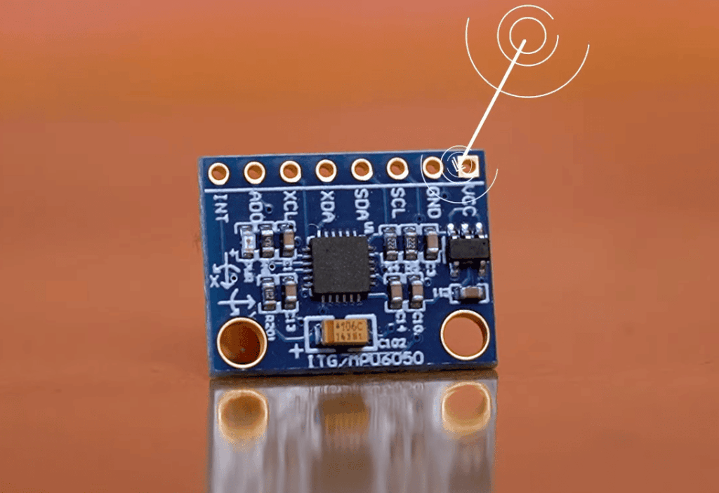
The module construction includes several key components. An LDO voltage regulator steps down power to 3.3V for the IC.
Decoupling capacitors filter electrical noise that could corrupt your data. Input/output headers handle power and data transfer efficiently.
All three sensors work together through internal processing. They combine measurements for complete motion, orientation, and direction tracking.
mpu9250 arduino: Interfacing and Connectivity
The bridge between physical hardware and digital intelligence begins with proper connection and setup. This section guides you through both the physical wiring and software preparation needed to get your motion tracking system operational.
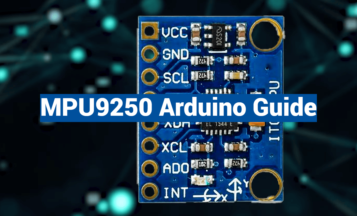
Hardware Connection: Wiring Diagrams and Pin Configurations
Establishing a reliable physical link is your first task. The most common approach uses the I2C bus, requiring just four essential wires between your microcontroller board and the sensor module.
For standard setups, connect VCC to 5V power, GND to ground, SDA to pin A4, and SCL to pin A5. Always verify your specific module can handle 5V input before making these connections. Advanced users can leverage additional pins like INT for interrupt-driven programming.
Software Setup: Installing Libraries and Arduino IDE Integration
Once physically connected, the software side brings your sensor arduino setup to life. Begin by installing the necessary library through the Arduino IDE Library Manager.
After installation, restart your development environment. You’ll then initialize serial communication to view real-time data from your gyroscope arduino system. The I2C protocol operates efficiently at 400kHz, ensuring smooth data transfer for your motion tracking applications.
Delving into Code Examples and Calibration Techniques
Once your hardware is properly connected, the next critical step involves writing code that transforms raw sensor readings into usable information. This process requires careful implementation of libraries and precise data handling.
Arduino Code Walkthrough
Your programming begins by including the essential Wire library for I2C communication. You’ll define specific addresses for the main sensor and magnetometer components.
The setup function initializes the I2C bus and starts serial communication. This allows you to monitor real-time data output. Configuring measurement ranges ensures your values stay within practical limits.
| Sensor Type | Measurement Range | Units |
|---|---|---|
| Accelerometer | ±2g to ±16g | g-force |
| Gyroscope | ±250 to ±2000 | °/sec |
| Magnetometer | ±4800 | µT |
In the main loop, your code reads 14 bytes from register 0x3B. This contains packed accelerometer and gyroscope data. The magnetometer requires checking status registers before reading its values.
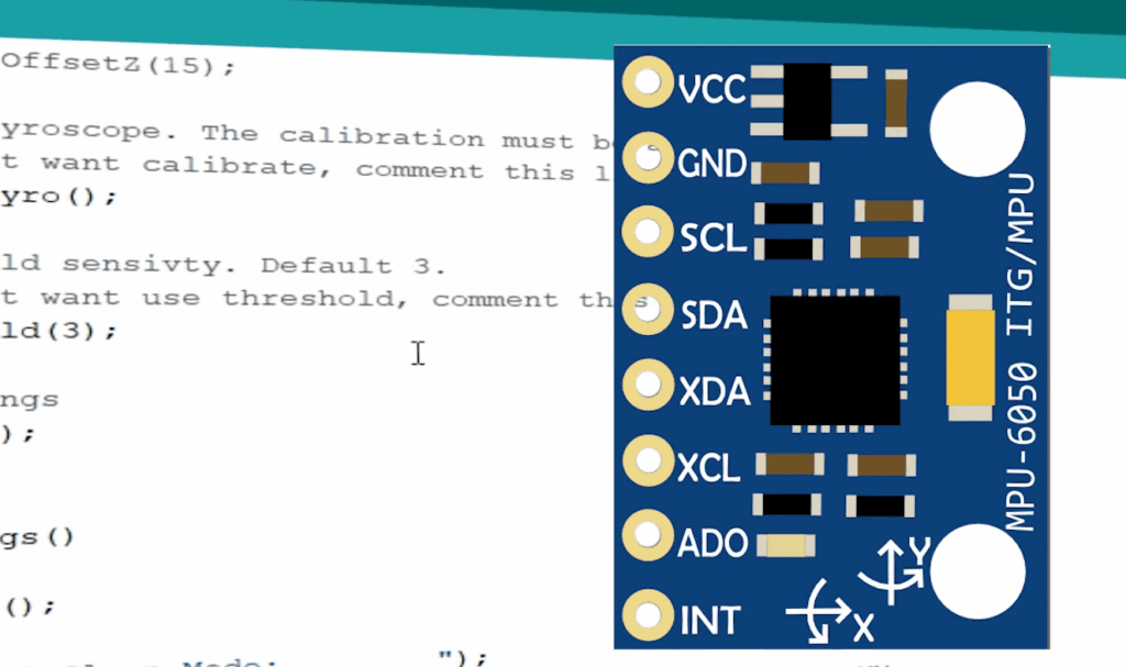
Calibration and Data Accuracy Tips
Calibration is essential for obtaining reliable readings. The magnetometer particularly needs careful adjustment to compensate for environmental influences.
Rotate the device through all orientations while recording maximum and minimum values. Calculate center points for each axis and apply these offsets to raw data. This process corrects for hard iron distortion.
Advanced functions like getHeading() use trigonometry to convert raw sensor data into practical orientation information. Always verify your connection before reading data to ensure accurate measurements.
Applications and Real-World Projects with MPU9250
From self-balancing vehicles to immersive gaming controllers, the practical applications of comprehensive motion detection span countless innovative fields. This versatile imu brings professional-grade capabilities to hobbyist projects and commercial products alike.
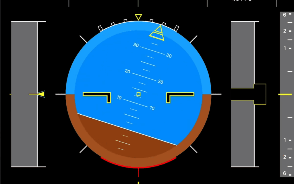
Innovative Uses in Motion and Navigation Projects
The integrated design of this sensor module enables remarkable project possibilities. Drones and aerial vehicles rely on its precise acceleration and orientation data for stable flight control.
Navigation systems benefit tremendously from the magnetometer’s drift correction. Robots and autonomous vehicles maintain accurate heading over extended time periods without cumulative errors.
Consumer electronics today incorporate similar technology for motion sensing. You can replicate smartphone features like screen rotation and step counting in your own devices.
Sports technology applications include swing analyzers and performance trackers. The precision measurements help athletes optimize their movements with detailed feedback.
Balancing robots and personal transporters use real-time data from the accelerometer and gyroscope. They maintain equilibrium through continuous adjustment based on motion inputs.
At around $3-4, this mpu9250 offers incredible value for advanced motion tracking. The affordable price makes sophisticated inertial measurement accessible to students and makers working with arduino boards.
Conclusion
You’ve reached the end of this comprehensive guide with all the tools needed to bring motion tracking to life. The journey from understanding basic components to practical implementation is now complete.
This powerful imu combines three essential sensors in one compact package. Its programmable range and precise clock ensure accurate data collection across various applications.
Remember that proper calibration transforms raw readings into reliable information. The connection between your microcontroller and this versatile sensor opens endless creative doors.
The mpu 9250 operates efficiently at low voltage, making it ideal for portable projects. Use the code example as your starting point, then customize for your specific needs.
Start building today and discover what you can create with this remarkable technology!