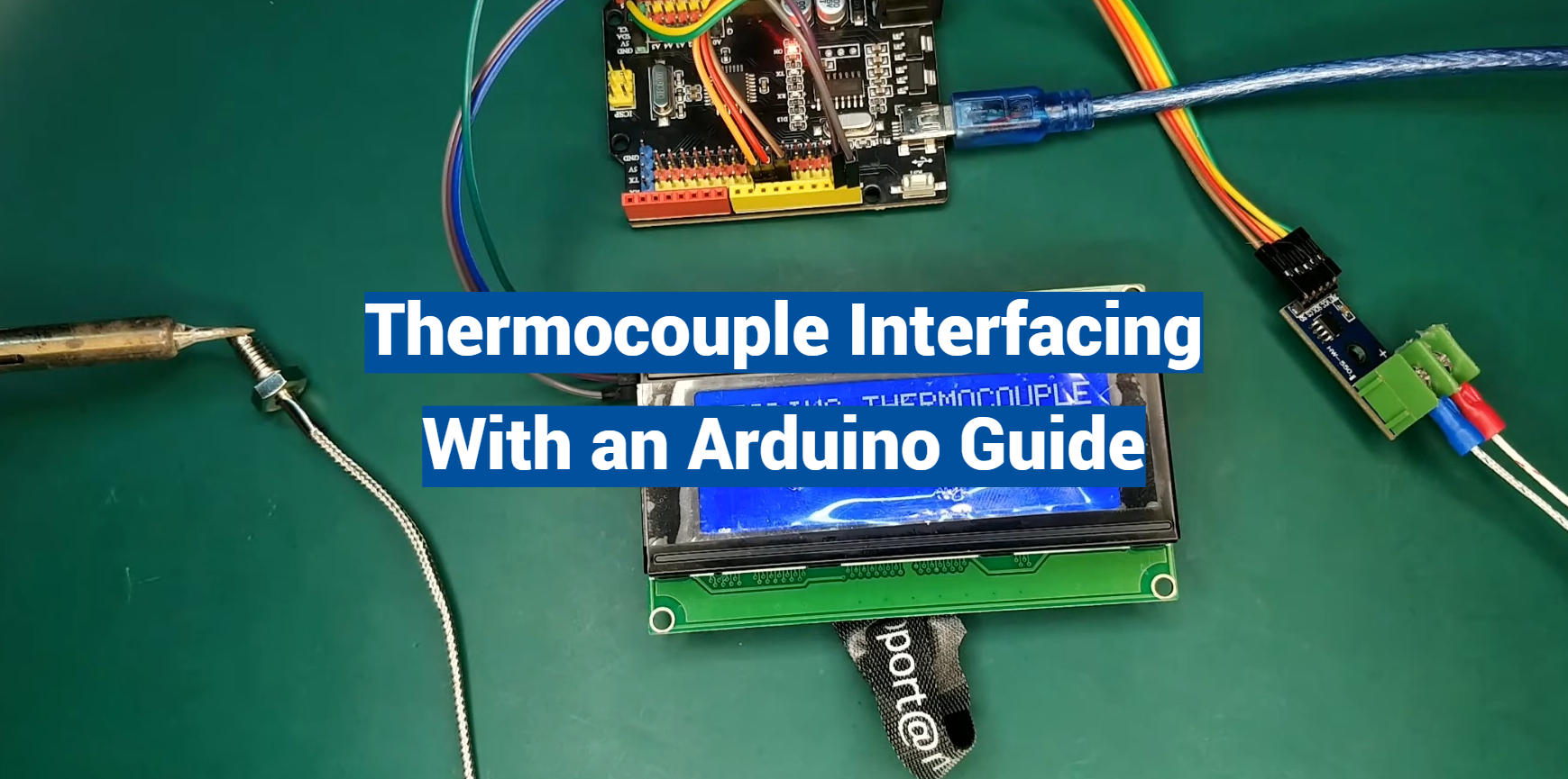
Embarking on a journey into the world of temperature sensing? This article provides a comprehensive step-by-step tutorial to connect a thermocouple to your Arduino. Thermocouples, with their ability to measure a wide range of temperatures, play a crucial role in multiple industries.
By interfacing it with an Arduino, you can create a precise and efficient temperature monitoring system for your projects. Whether you’re a hobbyist or a professional, this guide will equip you with the knowledge needed to successfully implement this versatile sensor in your Arduino-based applications.
Basics of Thermocouples
Thermoelectric Effect: The Foundation of Thermocouples
At the heart of thermocouples lies the thermoelectric effect, a fundamental phenomenon in physics. This effect, first discovered by Thomas Johann Seebeck in the early 19th century, involves the generation of an electric voltage at the junction of two different conductive materials when there is a temperature gradient between them. This electric voltage, often referred to as the Seebeck voltage, is directly proportional to the temperature difference between the two junctions [1].
The key to the thermoelectric effect lies in the dissimilar properties of the materials used in a thermocouple. These materials, known as thermoelements or thermocouple wires, typically consist of two different metals or metal alloys.
When one end of the thermocouple is exposed to a different temperature than the other end, a voltage is generated across the junction, which can be measured and used to determine the temperature difference.
Thermocouple Working: Harnessing the Thermoelectric Effect
The operation of a thermocouple is straightforward, relying on the thermoelectric effect to measure temperature accurately.
Here’s a step-by-step breakdown of how thermocouples work:
- Junctions: A thermocouple consists of two junctions: a hot junction and a cold junction. The hot junction is part of the thermocouple exposed to the temperature being measured, while the cold junction is usually maintained at a constant reference temperature, often referred to as the “reference junction” or “cold junction compensation”;
- Generation of Voltage: As mentioned earlier, when there is a temperature difference between the two junctions, the thermoelectric effect comes into play. This temperature gradient leads to the generation of an electric voltage at the hot junction due to the dissimilar properties of the thermoelements;
- Measurement: The voltage generated at the hot junction is proportional to the temperature difference between the hot and cold junctions. This voltage is then measured using specialized electronic equipment designed to capture the thermocouple’s output;
- Conversion: The voltage measured at the hot junction is converted into temperature readings using calibration tables or mathematical equations specific to the thermocouple type and the material composition of the thermoelements. These tables or equations are crucial for accurate temperature determination;
Thermocouple Wire Leads: Maintaining Accuracy and Reliability
To ensure accurate temperature measurements, the selection of thermocouple wire leads is critical. The wire leads are responsible for connecting the thermocouple junctions to the measuring instrument, and they play a significant role in maintaining the accuracy and reliability of the temperature readings [2].
Here are some essential considerations when it comes to thermocouple wire leads:
- Material Compatibility: The choice of thermocouple wire material is crucial, as different materials exhibit varying thermoelectric properties. It is essential to select materials that are compatible with the expected temperature range and environmental conditions of the application;
- Wire Insulation: Thermocouple wires are often insulated to prevent electrical interference and ensure accurate readings. The insulation material must be suitable for the intended application, taking into account factors such as temperature, moisture, and chemical exposure;
- Length and Size: The length and size of the thermocouple wire leads can impact the accuracy of the temperature measurement. Longer leads can introduce additional resistance, potentially affecting the voltage generated at the hot junction;
- Connection Methods: Proper connection methods, such as soldering or using specialized connectors, are essential to maintain the integrity of the thermocouple circuit. Loose or poorly connected leads can result in measurement errors;
Type-K Thermocouple: A Popular Choice
Among the various types of thermocouples available, the Type-K thermocouple stands out as one of the most commonly used and versatile options. Type-K thermocouples are known for their wide temperature range, high sensitivity, and accuracy.
Here are some key features of the Type-K thermocouple:
- Material Composition: Type-K thermocouples are made from chromel (Nickel-Chromium) and alumel (Nickel-Aluminum) alloys. These materials offer excellent performance across a broad temperature range, making Type-K thermocouples suitable for various applications;
- Temperature Range: Type-K thermocouples can measure temperatures ranging from approximately -200°C (-328°F) to 1,370°C (2,498°F). This extensive range makes them suitable for both low-temperature and high-temperature applications;
- Applications: Type-K thermocouples find application in industries such as manufacturing, aerospace, automotive, and food processing. They are also widely used in scientific research and experimentation;
- Accuracy: Type-K thermocouples offer good accuracy when used within their specified temperature range. However, it’s important to note that accuracy can vary depending on factors such as wire quality, insulation, and measurement equipment;
Thermocouple Digitizer: Enhancing Measurement Precision
To effectively utilize the temperature readings from thermocouples, a thermocouple digitizer, or temperature data acquisition system, is often employed.
A thermocouple digitizer serves several crucial functions in the measurement process:
- Signal Amplification: The voltage generated by a thermocouple is typically very low, especially when measuring small temperature differences. A thermocouple digitizer amplifies this signal to a level that can be accurately measured and recorded;
- Signal Conditioning: Temperature data often requires signal conditioning to compensate for factors such as lead resistance and non-linearity in the thermocouple’s response. A digitizer can apply correction algorithms to ensure precise measurements;
- Data Conversion: The analog voltage signal from the thermocouple is converted into a digital format for ease of processing, storage, and analysis. Digitizers typically employ analog-to-digital converters (ADCs) for this purpose;
- Data Logging: Thermocouple digitizers often include data logging capabilities, allowing for the continuous recording of temperature data over time. This is especially valuable in applications where temperature monitoring is critical, such as industrial processes and scientific experiments;
- Interface Options: Digitizers come with various interface options, such as USB, Ethernet, or wireless connectivity, enabling seamless integration with computer systems for real-time data monitoring and analysis;
Applications: Where Thermocouples Shine
Thermocouples are incredibly versatile temperature sensors, finding applications in a wide range of industries and scientific fields.
1. Industrial Processes
In industrial settings, thermocouples play a vital role in temperature monitoring and control.
They are employed in industries such as:
- Manufacturing: Thermocouples are used to monitor the temperature of machinery and materials during manufacturing processes, ensuring quality and safety;
- Petrochemical: In the petrochemical industry, thermocouples are used to measure the temperature of gases, liquids, and pipelines, helping to maintain the integrity of equipment;
- Food Processing: Temperature control is critical in food processing to ensure product safety and quality. Thermocouples are used to monitor cooking, refrigeration, and storage processes [3];
2. HVAC and Building Automation
In heating, ventilation, and air conditioning (HVAC) systems and building automation, thermocouples are employed for temperature regulation and energy efficiency:
- HVAC Systems: Thermocouples help control heating and cooling systems to maintain optimal indoor temperatures;
- Energy Management: Building automation systems use thermocouples to monitor temperature variations and adjust energy consumption accordingly;
3. Scientific Research
In scientific research and laboratories, precise temperature measurement is essential.
Thermocouples are used in various scientific disciplines, including physics, chemistry, and biology:
- Material Science: Researchers use thermocouples to study the thermal properties of materials and substances;
- Environmental Monitoring: Thermocouples are employed in environmental research to monitor temperature variations in ecosystems and climate studies;
4. Aerospace and Automotive
In aerospace and automotive industries, thermocouples are crucial for monitoring and ensuring the safety and performance of vehicles and aircraft:
- Engine Monitoring: Thermocouples are used to measure exhaust gas temperatures and engine performance in aircraft and automobiles;
- Space Exploration: In space missions, thermocouples help monitor temperature variations in spacecraft and scientific instruments;
5. Energy Generation
Thermocouples are used in power plants and energy generation facilities to monitor and control temperature in critical components like turbines, boilers, and heat exchangers:
- Geothermal Power Plants: Thermocouples are used to harness the Earth’s heat for power generation;
- Nuclear Power Plants: In nuclear facilities, thermocouples help maintain safe operating temperatures;
Overview of Thermocouple with Arduino:
Thermocouples, as we discussed earlier, are valuable temperature sensors that work on the thermoelectric effect. They can be easily integrated with microcontrollers like Arduino for accurate temperature measurements.
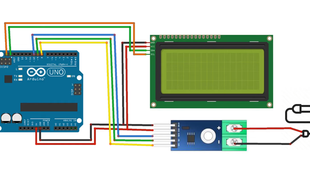
Connection Diagram of Thermocouple with Arduino
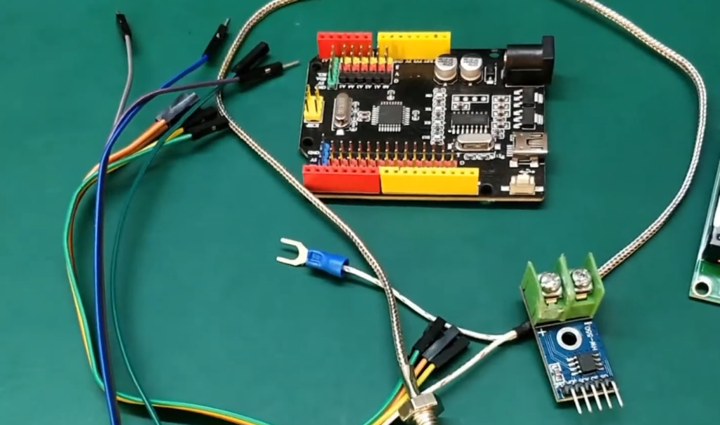
Before we dive into measuring temperature using a thermocouple and Arduino, it’s essential to establish the correct connections.
Here’s a connection diagram to guide you:
Connection Steps:
- Thermocouple Wires: Connect the two thermocouple wires (usually color-coded) to the input terminals of a thermocouple amplifier module or breakout board. The positive (red or yellow) wire connects to the positive terminal, and the negative (blue or white) wire connects to the negative terminal;
- Thermocouple Amplifier Module: Connect the output of the thermocouple to the appropriate pins on the thermocouple amplifier module. The module often includes an amplifier IC (such as the MAX31855 or MAX31856) that processes the thermocouple’s signal;
- Arduino: Connect the output pins of the thermocouple amplifier module to the corresponding pins on your Arduino board. This typically includes connections for SPI communication, such as MOSI (Master Out Slave In), MISO (Master In Slave Out), SCK (Serial Clock), and a CS (Chip Select) or SS (Slave Select) pin;
- Power Supply: Ensure that the thermocouple amplifier module receives the correct power supply voltage, typically 3.3V or 5V, depending on the module’s specifications. Connect the power supply to the VCC and GND (Ground) pins of the module [4];
Measure Temperature using a Thermocouple and Arduino Uno
Now that you have connected the thermocouple to your Arduino Uno, you can start measuring temperature.
Here’s a step-by-step guide on how to do it:
Initialize Libraries: Begin your Arduino sketch by including the necessary libraries for communication with the thermocouple amplifier module. Depending on the module you’re using, you might need to install and include specific libraries, such as “Adafruit_MAX31855.h” or “Adafruit_MAX31856.h.”.
#include
Define Pins: Declare the pins used for communication between the Arduino and the thermocouple amplifier module. These pins should match your wiring configuration.
#define MAX31855_CS_PIN 10 // Chip Select (CS/SS) pin
Create an Object: Create an instance of the thermocouple library, specifying the pins you defined earlier.
Adafruit_MAX31855 thermocouple(MAX31855_CS_PIN).
Setup Function: In the setup() function, initialize communication with the thermocouple amplifier module.
void setup() {
Serial.begin(9600);
thermocouple.begin();
}
Loop Function: In the loop() function, continuously read temperature values from the thermocouple and print them to the serial monitor.
cpp
Copy code
void loop() {
// Read temperature in Celsius
float temperature = thermocouple.readCelsius();
// Check for errors
if (isnan(temperature)) {
Serial.println(“Error reading thermocouple!”);
} else {
// Print temperature
Serial.print(“Temperature: “);
Serial.print(temperature);
Serial.println(” °C”);
}
delay(1000); // Delay for one second before the next reading
}
Upload and Monitor: Upload your Arduino sketch to the Arduino Uno and open the serial monitor (Tools > Serial Monitor). You should see the temperature readings in degrees Celsius [5].
Thermocouple Code for Arduino
Here is the complete Arduino code for reading temperature using a thermocouple and an Arduino Uno:
#include
#define MAX31855_CS_PIN 10
Adafruit_MAX31855 thermocouple(MAX31855_CS_PIN);
void setup() {
Serial.begin(9600);
thermocouple.begin();
}
void loop() {
float temperature = thermocouple.readCelsius();
if (isnan(temperature)) {
Serial.println(“Error reading thermocouple!”);
} else {
Serial.print(“Temperature: “);
Serial.print(temperature);
Serial.println(” °C”);
}
delay(1000);
}
With this code and the correct connections, your Arduino Uno will continuously read and display temperature values from the thermocouple on the serial monitor.
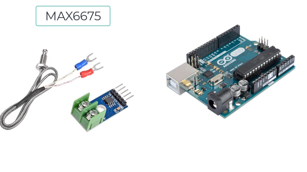
MAX6675 Thermocouple Module:
The MAX6675 thermocouple module is a versatile and reliable device for measuring temperature using Type-K thermocouples. This compact module is a popular choice among electronics enthusiasts and engineers due to its simplicity and precision.
What Is the MAX6675 Thermocouple Module?
This module is specifically designed to work with Type-K thermocouples, which are known for their wide temperature measurement range and high accuracy. By using the MAX6675 module, you can convert the tiny voltage generated by the thermocouple into digital temperature readings that are easy to read, store, and analyze.
MAX6675 Breakout: Simplifying Connections
To make the MAX6675 module more accessible and user-friendly, breakout boards are commonly used. A breakout board is a PCB (Printed Circuit Board) that provides a convenient interface for connecting the MAX6675 module to other components, such as microcontrollers like Arduino [6]. Breakout boards typically include connectors, voltage regulation circuitry, and pull-up resistors, simplifying the overall setup.
The MAX6675 breakout board often comes with clearly labeled pins and connectors, making it easier to connect wires and integrate the module into your projects. It also helps protect the MAX6675 module and prevents accidental damage during handling and experimentation.
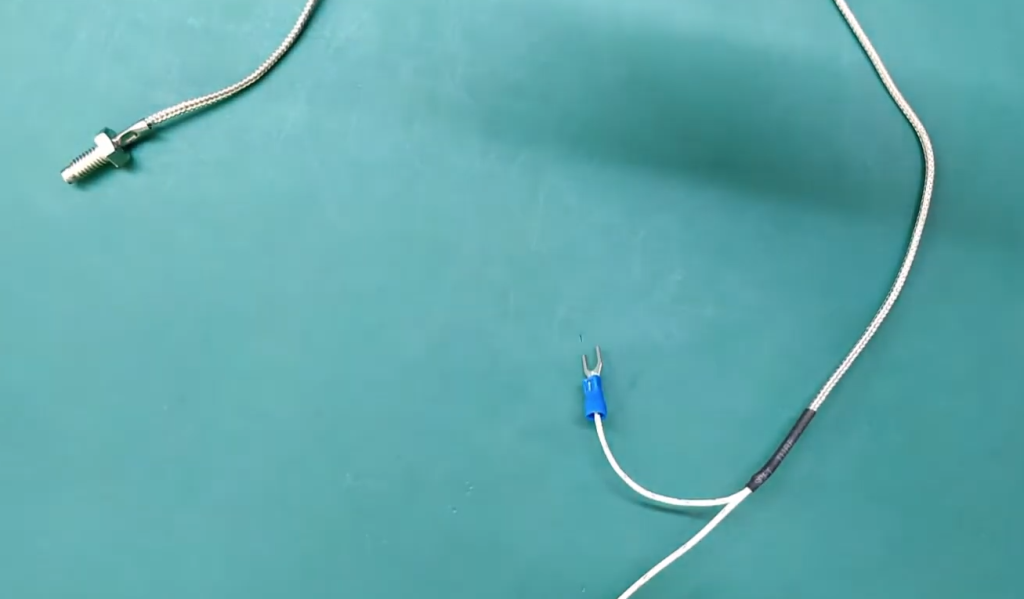
Type-K Thermocouple Probe: Measuring Temperature with Precision
A critical component of the MAX6675 module is the Type-K thermocouple probe. Type-K thermocouples are widely recognized for their accuracy and versatility in temperature measurement. These thermocouples consist of two different metal alloys, typically chromel (Nickel-Chromium) and alumel (Nickel-Aluminum).
The Type-K thermocouple probe is responsible for capturing temperature variations in the environment or within a system. When one end of the probe is exposed to a different temperature than the other end, it generates a small voltage due to the Seebeck effect, which is then detected and processed by the MAX6675 module.
The key advantages of Type-K thermocouples include their wide temperature measurement range, durability, and compatibility with various applications, making them a popular choice in many industries.
Technical Specifications
To understand the capabilities and limitations of the MAX6675 thermocouple module, it’s essential to review its technical specifications.
Here are the key specifications of the MAX6675:
- Temperature Range: The MAX6675 can measure temperatures ranging from approximately -200°C to 1,025°C (-328°F to 1,877°F). This broad range makes it suitable for various applications, including both low-temperature and high-temperature environments;
- Resolution: The module provides temperature readings with a resolution of 0.25°C (0.45°F). This level of precision allows for accurate monitoring and control of temperature-sensitive processes;
- Output Format: The MAX6675 outputs temperature data in a digital format, specifically in degrees Celsius. This makes it easy to interface with microcontrollers and digital displays;
- Interface: It uses a simple SPI (Serial Peripheral Interface) communication protocol, which requires minimal wiring and can be easily integrated into microcontroller projects;
- Supply Voltage: The module typically operates on a supply voltage of 3.3V or 5V, making it compatible with a wide range of microcontrollers and development boards;
- Accuracy: The MAX6675 has an accuracy of ±2°C (±3.6°F) within its specified temperature range. This level of accuracy is suitable for most applications;
- Cold Junction Compensation: It includes built-in cold junction compensation, ensuring accurate temperature measurements even when the reference junction (cold junction) temperature varies [7];
Now that we have a solid understanding of the MAX6675 module and its technical specifications, let’s explore its pinout and how to interface it with an Arduino microcontroller.
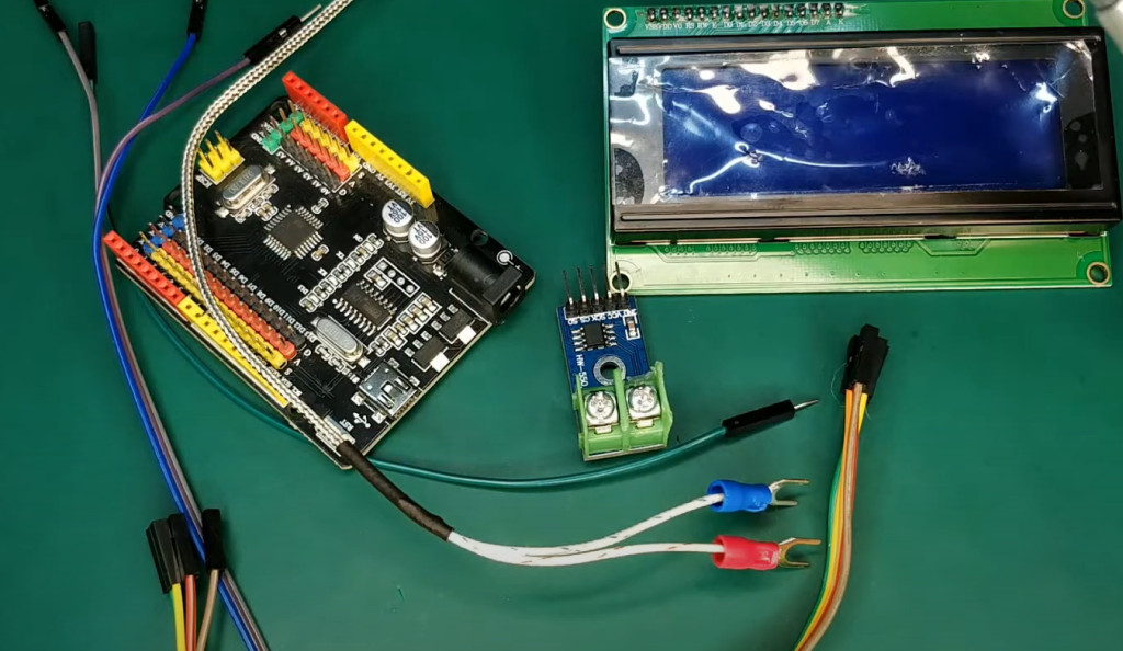
MAX6675 Module Pinout: Making the Right Connections
The correct connection of the MAX6675 module is crucial for obtaining accurate temperature measurements. Let’s break down the module’s pinout and understand the purpose of each pin.
Input Connector:
- VCC: This pin is used to supply power to the MAX6675 module. It typically operates at 3.3V or 5V, depending on your application and microcontroller compatibility;
- GND: Connect this pin to the ground (0V) of your power supply or microcontroller to complete the circuit;
- SCK (Serial Clock): SCK is the serial clock pin used for SPI communication. It synchronizes data transmission between the MAX6675 and your microcontroller;
- CS (Chip Select): The CS pin, also known as SS (Slave Select), is used to select the MAX6675 module for communication. It enables and disables communication between the microcontroller and the module;
Thermocouple Connector:
- SO (Serial Data Output): SO is the serial data output pin. This is where the MAX6675 sends temperature data in digital form to your microcontroller;
- NC (No Connection): This pin is typically not connected and remains unused;
Now that we’re familiar with the pinout, let’s move on to interfacing the MAX6675 thermocouple module with an Arduino microcontroller.
Interfacing MAX6675 Thermocouple Module with Arduino
Interfacing the MAX6675 thermocouple module with an Arduino is a straightforward process that involves connecting the module to the Arduino, installing the necessary libraries, and writing code to read and display temperature data.
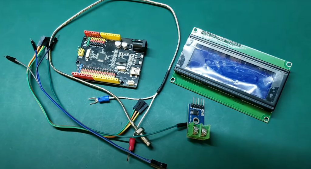
Required Materials:
- MAX6675 thermocouple module with breakout board;
- Type-K thermocouple probe;
- Arduino microcontroller (e.g., Arduino Uno);
- Jumper wires;
- Computer with the Arduino IDE installed;
Hardware Components:
- MAX6675 Module: Begin by connecting the MAX6675 module to your Arduino. Follow the pinout connections mentioned earlier to ensure the correct wiring;
- Type-K Thermocouple Probe: Attach the Type-K thermocouple probe to the input terminals of the MAX6675 module. Ensure a secure and proper connection to obtain accurate temperature readings;
- Arduino: Connect your Arduino to the MAX6675 module using jumper wires. Ensure that you connect the SCK, CS, and SO pins correctly between the module and the Arduino;
Software Apps:
To program your Arduino and interface with the MAX6675 module, you’ll need the Arduino IDE, which can be downloaded from the official Arduino website.
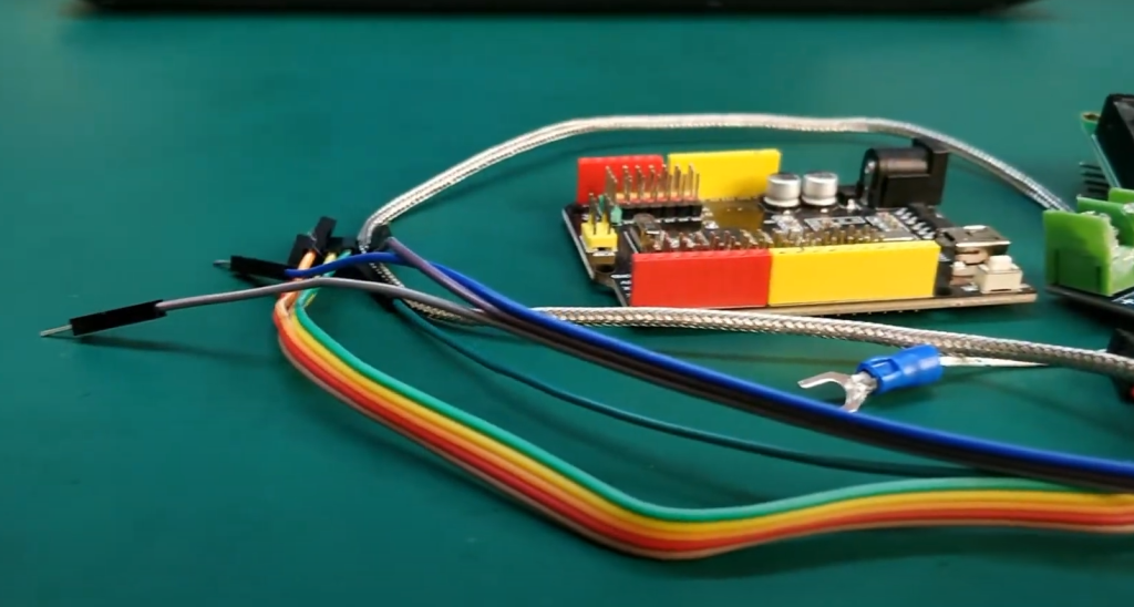
Circuit:
The circuit connections between the MAX6675 module and an Arduino are relatively straightforward.
Here’s a brief overview of the connections:
- Connect the VCC pin of the MAX6675 module to the 5V output of the Arduino or to a separate 5V power supply if needed;
- Connect the GND pin of the MAX6675 module to the GND (Ground) of the Arduino;
- Connect the SCK pin of the MAX6675 module to the SCK (Serial Clock) pin of the Arduino;
- Connect the CS pin of the MAX6675 module to any digital pin of the Arduino (e.g., digital pin 10);
- Connect the SO pin of the MAX6675 module to the MISO (Master In Slave Out) pin of the Arduino;
Library Installation:
To facilitate communication between the MAX6675 module and the Arduino, you’ll need to install the appropriate library. In the Arduino IDE, follow these steps:
- Go to “Sketch” > “Include Library” > “Manage Libraries…”;
- In the Library Manager, search for “Adafruit MAX6675”;
- Click “Install” to install the library;
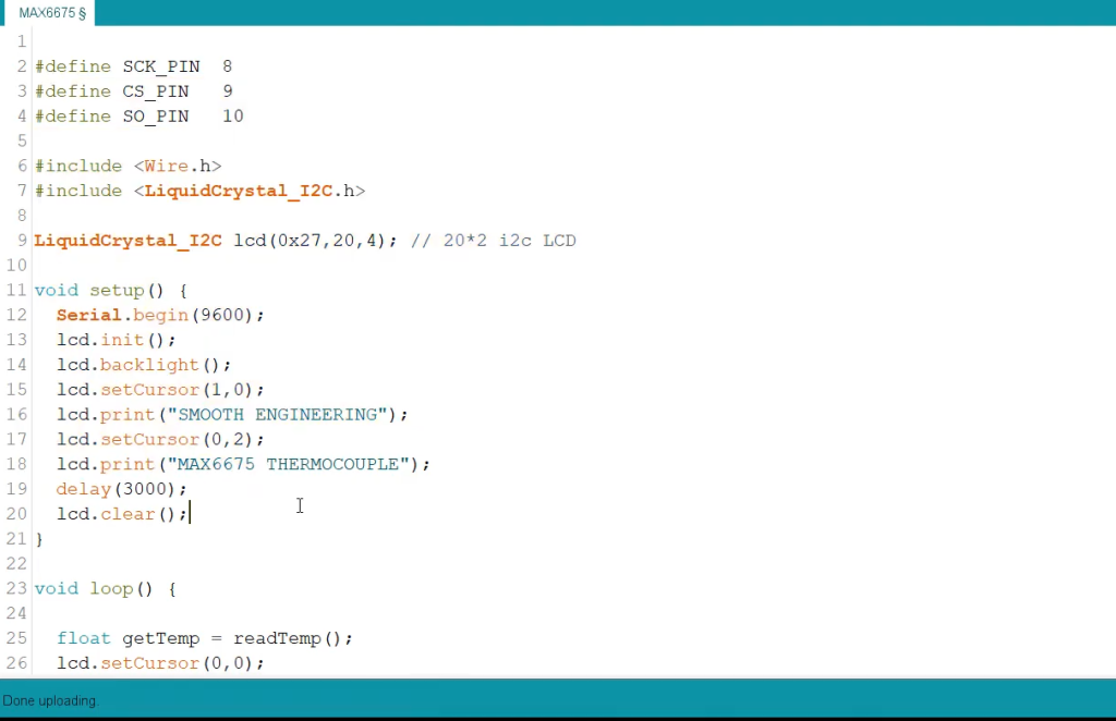
Code:
Now, let’s write an Arduino sketch to read temperature data from the MAX6675 module and display it on the serial monitor. Here’s a sample code:
#include
// Define the connections to the MAX6675 module
#define MAX6675_CLK 13
#define MAX6675_CS 10
#define MAX6675_DO 12
Adafruit_MAX6675 thermocouple(MAX6675_CLK, MAX6675_CS, MAX6675_DO);
void setup() {
Serial.begin(9600);
Serial.println(“MAX6675 Test”);
thermocouple.begin();
}
void loop() {
// Read temperature in Celsius
float temperatureC = thermocouple.readCelsius();
if (isnan(temperatureC)) {
Serial.println(“Error reading thermocouple!”);
} else {
Serial.print(“Temperature: “);
Serial.print(temperatureC);
Serial.println(” °C”);
}
delay(1000); // Delay for one second before the next reading
}
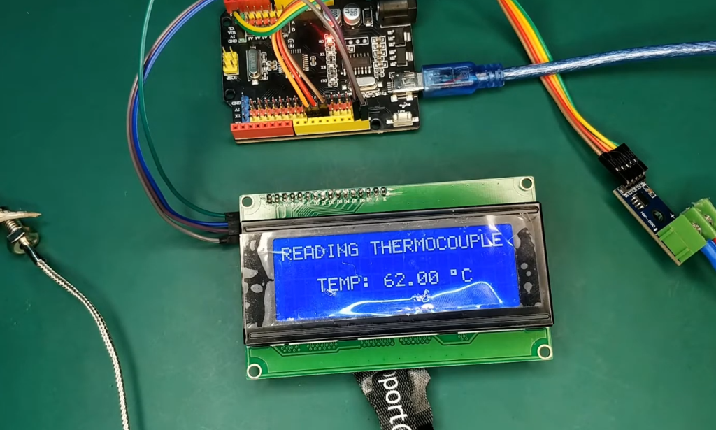
This code initializes the MAX6675 module, reads temperature data in degrees Celsius, and displays it on the serial monitor. Make sure your Arduino is connected to your computer, select the correct board and port in the Arduino IDE, and upload the code.
You should now see temperature readings in degrees Celsius on the serial monitor.
FAQ:
1. How to connect a thermocouple with Arduino?
Connecting a thermocouple to an Arduino involves several steps:
- Select the Right Thermocouple: First, choose the appropriate type of thermocouple for your application, such as Type-K, Type-T, etc.;
- Connect the Thermocouple Wires: Connect the two wires of the thermocouple to the input terminals of a thermocouple amplifier module or breakout board. Ensure that the positive wire (usually red or yellow) connects to the positive terminal and the negative wire (typically blue or white) connects to the negative terminal;
- Connect the Thermocouple Amplifier Module: Connect the output pins of the thermocouple amplifier module to the corresponding pins on your Arduino. This typically includes connections for SPI communication, such as MOSI, MISO, SCK, and a CS or SS pin;
- Power Supply: Provide the thermocouple amplifier module with the required power supply voltage (usually 3.3V or 5V) by connecting it to the VCC and GND (Ground) pins;
- Code and Read Data: Write Arduino code to read and process the temperature data from the thermocouple amplifier module. This may involve installing the appropriate library and using SPI communication to retrieve temperature readings;
2. How to read a K-type thermocouple with Arduino?
To read a K-type thermocouple with an Arduino, follow these steps:
- Select a K-type Thermocouple: Ensure you have a K-type thermocouple probe, which is compatible with the Arduino;
- Connect the Thermocouple: Connect the two wires of the K-type thermocouple to a thermocouple amplifier module or breakout board;
- Connect to Arduino: Wire the output pins of the thermocouple amplifier module to the Arduino’s SPI pins (MOSI, MISO, SCK, and CS) and connect the power supply (VCC and GND) to the appropriate voltage source;
- Install Libraries: In the Arduino IDE, install the relevant library (e.g., “Adafruit_MAX6675”) to facilitate communication with the MAX6675 thermocouple amplifier;
- Write Code: Write Arduino code to read temperature data from the thermocouple. Use the library functions to interface with the MAX6675 module and display temperature readings on the serial monitor;
- Upload and Monitor: Upload the code to the Arduino and open the serial monitor to view real-time temperature data from the K-type thermocouple;
3. Can Arduino read thermocouples?
Yes, an Arduino can read a thermocouple by using a thermocouple amplifier module like the MAX6675 or MAX31855. These amplifier modules convert the voltage generated by the thermocouple into digital temperature data that can be read and processed by the Arduino. By interfacing the Arduino with such a module and writing the appropriate code, you can accurately read and utilize temperature information from the thermocouple.
4. How do you attach a thermocouple?
Attaching a thermocouple involves connecting its two wires to the input terminals of a thermocouple amplifier module or breakout board. Ensure that the positive wire (usually red or yellow) is connected to the positive terminal, and the negative wire (typically blue or white) is connected to the negative terminal. The connection should be secure to obtain accurate temperature readings.
5. How many thermocouples can I connect to Arduino?
The number of thermocouples you can connect to an Arduino depends on factors such as the availability of input pins, the type of thermocouple amplifier modules used, and the microcontroller’s processing capabilities.
In practice, you can connect multiple thermocouples to a single Arduino by using multiple thermocouple amplifier modules and sharing the Arduino’s SPI pins for communication. However, the specific number of thermocouples you can connect will vary based on your project’s requirements and the microcontroller’s limitations.
6. What is the input voltage of a thermocouple?
A thermocouple itself does not require a specific input voltage. Instead, it generates a voltage when exposed to a temperature gradient, and this voltage is typically very low, on the order of millivolts.
To measure the temperature using a thermocouple, you need a thermocouple amplifier module that provides the required voltage and converts the thermocouple’s output into a usable signal, often at 3.3V or 5V for Arduino compatibility.
7. How does a thermocouple generate voltage?
A thermocouple generates voltage through the thermoelectric effect, also known as the Seebeck effect. It occurs when two dissimilar metals or metal alloys are joined at one end, creating a junction. When this junction is exposed to a temperature gradient, a voltage difference is produced across the junction. This voltage is proportional to the temperature difference between the hot and cold ends of the thermocouple and can be measured to determine the temperature.
8. What are the 2 wires for a thermocouple?
The two wires on a thermocouple are positive and negative wires. These wires are made of different metals or metal alloys and are joined at one end to create a thermocouple junction. When the temperature at one end of the thermocouple differs from the temperature at the other end, it generates a voltage difference between these two wires, which is proportional to the temperature difference.
9. Does a thermocouple have 2 wires?
Yes, a thermocouple typically has two wires: a positive wire and a negative wire. These two wires are essential for generating the voltage signal that is proportional to the temperature difference between the hot and cold ends of the thermocouple. The voltage generated is used for temperature measurement.
10. How to connect a thermocouple to PLC?
To connect a thermocouple to a programmable logic controller (PLC), follow these steps:
- Select the appropriate type of thermocouple (e.g., Type-K) for your application;
- Connect the two wires of the thermocouple to a thermocouple amplifier module or transmitter. This module will provide signal conditioning and conversion to a PLC-compatible signal;
- Wire the output of the thermocouple amplifier module to the analog input or dedicated thermocouple input terminals on the PLC;
- Configure the PLC’s software to read and process the temperature data from the thermocouple. You may need to set up scaling and unit conversion based on the thermocouple type;
- Monitor and log temperature data using the PLC’s control software or human-machine interface (HMI);
11. How do I choose a thermocouple?
Choosing a thermocouple involves considering several factors, including:
- Temperature Range: Select a thermocouple type that covers the temperature range of your application;
- Accuracy: Consider the required accuracy for temperature measurement;
- Chemical Compatibility: Ensure that the thermocouple materials are compatible with the environment or substances it will be exposed to;
- Mechanical Strength: Choose a thermocouple that can withstand any mechanical stress or vibrations in the application;
- Response Time: Evaluate the desired response time for temperature changes;
- Cost: Take into account the budget for the thermocouple;
- Environmental Conditions: Consider factors like pressure, humidity, and the presence of corrosive gases;
Consult thermocouple reference tables and charts to make an informed choice.
12. Do thermocouples need special connectors?
Thermocouples often require special connectors to ensure accurate and reliable connections. These connectors are designed to match the specific thermocouple type and provide proper insulation and protection. Common thermocouple connector types include mini connectors, standard connectors, and high-temperature connectors.
Using the correct connector is crucial for maintaining the accuracy of temperature measurements and preventing signal interference.
Useful Video: How to interface MAX6675 with Arduino | Thermocouple
References:
- https://www.electronicwings.com/arduino/thermocouple-interfacing-with-arduino-uno
- https://randomnerdtutorials.com/arduino-k-type-thermocouple-max6675/
- https://electropeak.com/learn/interfacing-max6675-k-type-thermocouple-module-with-arduino/
- https://lastminuteengineers.com/max6675-thermocouple-arduino-tutorial/
- https://bestengineeringprojects.com/how-to-arduino-thermocouple-interface/
- https://www.instructables.com/Thermocouple-Amplifier-and-K-Type-Thermocouple-Int/
- https://www.electronics360.org/interfacing-max31855-thermocouple-amplifier-with-arduino/