Step into the fascinating world of electrical engineering as we delve into the electrifying realm of delay circuits. Have you ever wondered how electronic devices manage to time their actions flawlessly, creating the perfect sequence of events? Look no further, as this guide unravels the mysteries behind delay circuits and explores their significance in the world of technology. Whether you’re a beginner exploring the foundations of electrical engineering or a seasoned expert looking to expand your knowledge, this article will provide you with a comprehensive understanding of what a delay circuit is and how it functions. So, fasten your seatbelts and get ready for an electrifying journey into the heart of delay circuits.
What is a Delay Circuit for?
Delay circuits have various advantages over other timing methods. They can be easily adjusted for different time intervals in real time, they don’t create any noise or distortion when operating, and they require minimal power consumption. Furthermore, delay circuits can be used to control multiple devices simultaneously without the need for additional hardware or software.
Delay circuits are often used in applications such as audio processing, instrumentation, robotics, and security systems. For example, they can be used to create precise delays for triggering alarms or relays in security systems. In audio processing applications, delay circuits are typically used to create effects such as echo and chorus. They can also be employed in complex instruments such as sequencers and synthesizers. Delay circuits are also used in robotics to time operations that require precise delays, such as opening and closing valves or moving robotic arms.
The design of delay circuits typically involves the use of capacitors, resistors, and transistors which are connected appropriately. The resistor-capacitor circuit (RC Circuit) is one of the most widely used types of delay circuits and consists of a resistor connected in series with a capacitor. The RC circuit is commonly used for creating delays because it can be easily adjusted to different time intervals by changing the value of either the resistor or capacitor. Other types of delay circuits include diode-capacitor (DC) circuits, multivibrator circuits, and transistor-capacitor (TC) circuits.
Regardless of the type of delay circuit used, all of them are designed to provide precise timing signals for various applications. Delay circuits are often used in combination with other electronic components such as logic gates and amplifiers to create complex systems with a wide range of functions. They can also be combined with microcontrollers and programmable logic devices to create more sophisticated systems.
In conclusion, delay circuits are essential components of any electronic system as they provide precise timing signals and can be easily adjusted for different time intervals. Delay circuits are used in a variety of applications such as audio processing, instrumentation, robotics, and security systems. They are typically designed with resistors, capacitors, transistors, and other components. By combining delay circuits with other electronic components, complex systems can be designed for a wide range of applications [1].
6 Types of Delay Circuits Explained
Precise long delay circuit
This type of circuit is especially useful for applications that need a precise delay, such as time-lapse photography. It uses an LM555 timer IC to produce a specific number of pulses at regular intervals over a long period. The output can then be used to activate another device or be measured against a reference voltage to calculate the amount of delay desired. The circuit consists of two components, the timer IC and a capacitor. The capacitor is charged up to a certain voltage level and then discharged over an adjustable period. This period can be adjusted by changing the value of the resistor connected to the LM555.
RC delay circuit
This type of circuit is used to delay a signal for a short period. It consists of an RC network, which is connected in series with the input signal and output load. The capacitor charges up slowly over time and then discharges rapidly when triggered by the input signal. This produces a short delay that can be tuned according to the values of the resistor and capacitor. The advantage of this circuit is that it can be used with both AC and DC signals.
555 Simple long delay circuit
This circuit uses a 555 timer IC to produce a long delay of up to several hours. The resistor and capacitor values can be adjusted to obtain the desired delay time. The 555 is triggered by an input signal that sets the timer off and produces an output pulse at the end of the delay period. This output pulse can then be used to activate another device or serve as an indicator for the amount of time elapsed.
Long-delay circuit consisting of two 555 time-based circuits
This type of circuit is used to produce a long delay that can be adjusted according to the user’s needs. It consists of two 555 timer ICs connected in series and triggered by an input signal. The first 555 produces a short pulse at its output when it is triggered, while the second one produces a longer pulse after the initial short pulse has ended. This combination of pulses can be used to produce a long delay by adjusting the resistor and capacitor values of both the ICs.
Monostable delay circuit with a single op-amp
This type of circuit uses a single op-amp to produce an adjustable delay. The circuit consists of an RC network, which is connected in series with the input and output signals. When the input signal is applied, it charges up the capacitor slowly and then discharges rapidly when triggered by the op-amp. The resistance and capacitance values can be adjusted to obtain the desired delay time.
Transistor delay circuit
This type of circuit uses a transistor to produce an adjustable delay. It consists of a transistor and a resistor connected in series. When the input signal is applied, it triggers the transistor which produces an output pulse at its collector. The delay time can be adjusted by changing the value of the resistor. This type of circuit is commonly used in applications where long delays are required such as in home automation systems [2].
Logic circuit delay
This type of circuit uses logic gates to produce an adjustable delay. It consists of a series of logic gates connected in series with the input and output signals. When the input signal is applied, it triggers the logic gates which produce an output pulse at its collector. The delay time can be adjusted by changing the logic gates used. This type of circuit is commonly used in applications where short delays are required such as in digital systems.
How Does a Time-Delay Circuit Work?
Time-delay circuits are a type of electronic circuit that can be used to control the timing of other circuits. A time-delay circuit can act as an ON/OFF switch, or it can provide an adjustable delay between when one circuit is activated and when another circuit is activated. For example, a time-delay circuit could be used in a security system to delay the activation of an alarm for a given amount of time.
Time-delay circuits are typically composed of two main components: a timer and a power source. The timer is responsible for controlling the length of time before the circuit is activated, while the power source provides power to the circuit. When the timer reaches its preset value, it will trigger the output of the circuit, which will then activate the other circuits or devices connected to it.
Time-delay circuits can also be used in a variety of other applications. For example, they can be used to control the speed of motors, adjust the brightness of lights, and automate processes such as production lines. They are also often used in industrial control systems, where they provide precise timing for processes such as hydraulic and pneumatic systems. Time-delay circuits are highly reliable and can be easily programmed to provide the exact timing needed for a particular application.
Time-delay circuits can also be used to create short pauses in between operations, allowing for more efficient operation of machines or processes. For example, a time-delay circuit could be used in an automotive assembly line to provide a brief pause between when the parts are assembled and when they are inspected. This can help ensure that any final adjustments or repairs are completed before the parts move on to the next station in the process. By using time-delay circuits, manufacturers can improve their efficiency and reduce waste by eliminating unnecessary production delays [3].
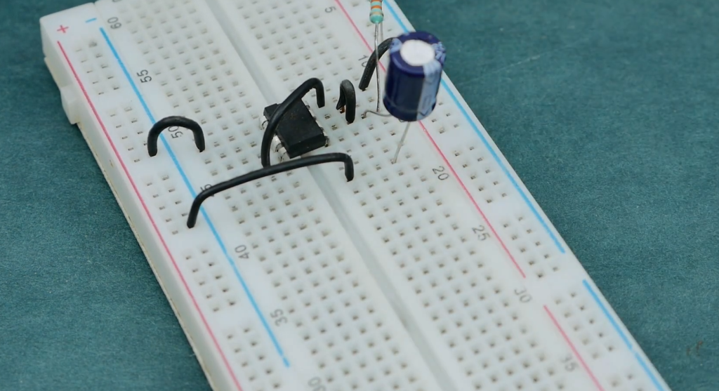
Building a Time Delay Circuit
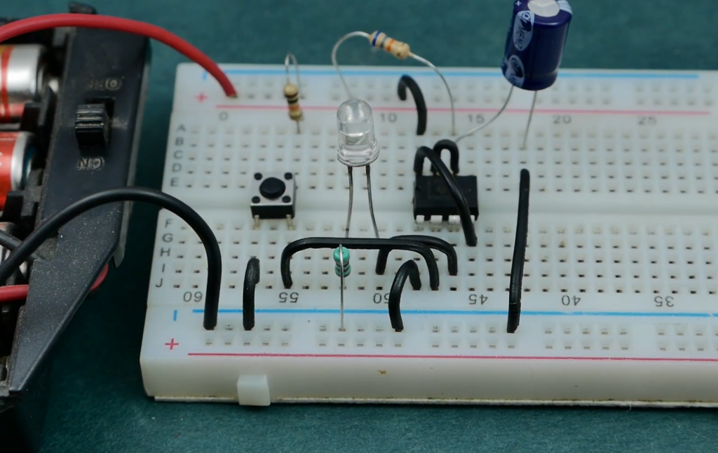
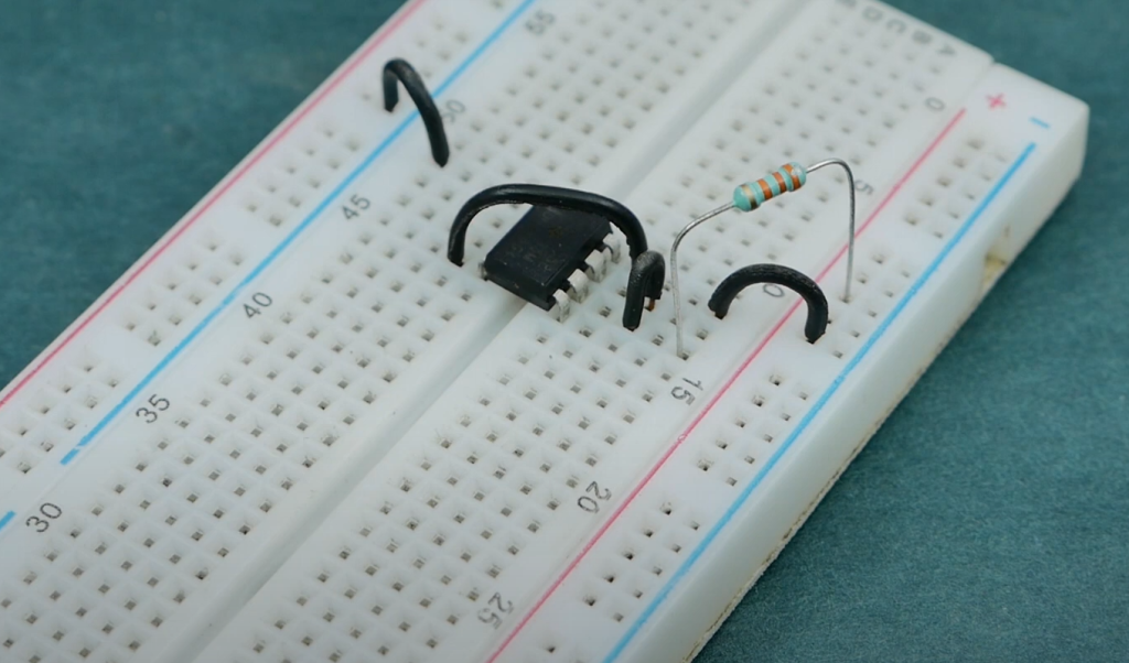
Components Required
To build a time delay circuit, you will need some basic components. These include:
- A transistor
- A resistor
- An LED (light emitting diode)
- Some hookup wire
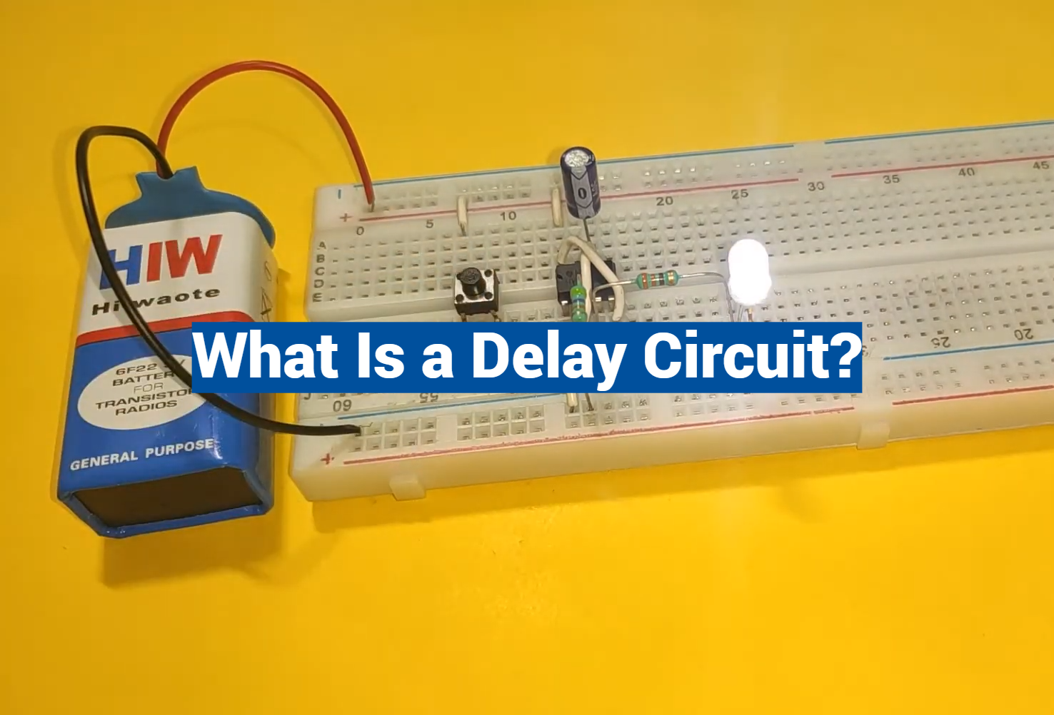
Connecting the Components Together
Once all of the necessary components have been gathered, it is time to start connecting them together. Begin by carefully connecting the positive lead of the LED to one end of the resistor, ensuring a secure connection. Next, connect the collector terminal of the transistor to the other end of the resistor, making sure the connection is firm. Finally, use the hookup wire to connect the emitter terminal of the transistor to the negative lead of the LED, completing the circuit. Double-check all connections to ensure they are properly secured and ready for use.
Calibration
Once all the components are properly connected, it is time to proceed with the calibration of the circuit. This crucial step involves fine-tuning the values of each component to achieve the desired delay. It is important to note that each component may require different adjustment methods, so it is essential to thoroughly familiarize yourself with the specific techniques required for each component. By taking the time to understand and apply the appropriate adjustments, you can ensure optimal performance and accuracy in your circuit. So, get ready to dive into the intricate world of circuit calibration and unleash the full potential of your electronic masterpiece!
Working Principles
Once the circuit is calibrated, it is time to delve into understanding its inner workings. The transistor, a key component, functions as a switch that can be toggled on or off based on the voltage applied to it. When the voltage surpasses a particular threshold, the transistor activates, allowing current to flow through the LED. However, when the voltage drops below this threshold, the transistor deactivates, effectively blocking the current and causing a delay in the circuit’s operation. This intricate interplay between voltage levels and transistor behavior contributes to the fascinating dynamics of the circuit.
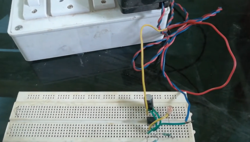
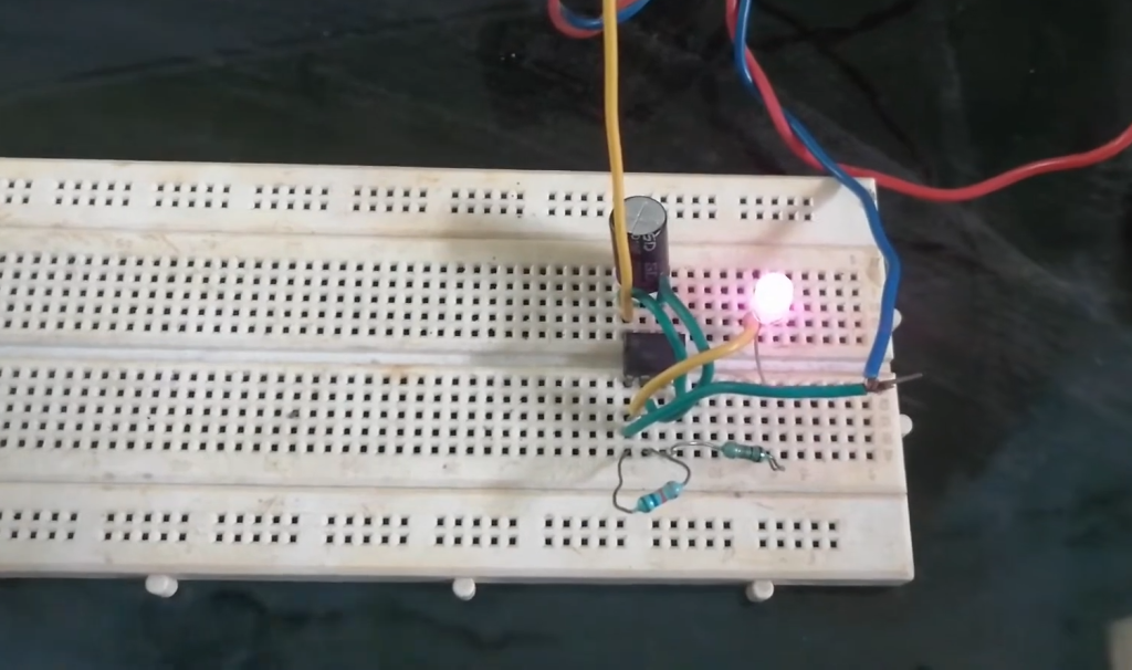
Testing
Finally, it is time to test the circuit. Once the calibration has been completed, you can connect a power source and use a timer to measure the exact amount of time that passes before the LED turns on. This will tell you if the circuit has been built and calibrated correctly.
Time-delay Circuit Applications
Flashing light control (time on, time off)
Time-delay circuits are especially useful for controlling flashing lights. A typical application is a roadway warning light, such as for construction zones. The time-delay circuit allows the light to stay on for a predetermined amount of time and then turn off until it is triggered again. This eliminates the need to manually reset the system each time the light needs to be activated.
Engine auto start control
Time-delay circuits can also be used to control engine auto start systems. In this system, the time delay circuit allows for the engine to start at a predetermined interval, such as once every hour or once every day. This eliminates the need for manual intervention and ensures that the engine is running at peak efficiency and reliability.
Furnace safety purge control
Time-delay circuits can also be used for furnace safety purge control. This system permits the furnace to start automatically at a predetermined interval, such as once every hour or once every day. The time delay circuit ensures that the furnace is purged of any dangerous gasses before it is activated and safely operates at peak efficiency.
Motor soft-start delay control
Time-delay circuits are highly beneficial not only for motor soft-start delay control but also for various other applications. One such application is in the domain of power electronics, where time-delay circuits play a crucial role in protecting sensitive electronic components. By allowing motors to start slowly and gradually increase speed at a predetermined interval, these circuits ensure a smooth and controlled power-up sequence. This not only prevents sudden surges in power that can potentially damage the motor and connected components but also extends the lifespan of the entire system. With their ability to provide precise timing control, time-delay circuits have become an indispensable tool in many industries, offering enhanced performance, reliability, and protection.
Conveyor belt sequence delay control
Time-delay circuits are incredibly useful in industrial settings for precisely controlling conveyor belt sequences. By incorporating this system, the conveyor belt is programmed to initiate movement only after a specific period has elapsed. This meticulous timing ensures that the entire sequence runs seamlessly and with optimal efficiency, eliminating any potential for sudden jolts or interruptions in the operation. As a result, productivity and overall performance are enhanced, allowing for a more streamlined and reliable workflow.
Automatic Shut-off (time on, time off)
Time-delay circuits are versatile tools that can be utilized to control the automatic shut-off of various devices, including printers or radios. By precisely setting the desired duration before the device powers down, the need for manual intervention is eliminated, thereby saving valuable time and energy. This intelligent feature not only ensures convenience but also promotes safety by guaranteeing that devices are securely turned off when not in use. Embracing such efficient mechanisms allows for enhanced productivity and reduced energy consumption, contributing to a more sustainable and streamlined technological experience.
FAQ
Which can be used as a delay circuit?
A delay circuit can be used to introduce a time gap between two events. Common types of delay circuits include analog and digital timers, inverters, pulse generator circuits, oscillators, and various types of logic gates. Depending on the application, one or more components may also be included in the circuit for greater control over timing accuracy and other factors. Additionally, some delay circuits feature LEDs or other output indicators that can help the user track progress through a sequence of events.
What is an oscillator circuit?
An oscillator circuit is a type of electronic circuit used to generate a continuous periodic signal, usually in the form of sine waves. Many different types of oscillators are commonly used in various applications, including radio communication, audio production, and other types of signal processing. Oscillator circuits typically consist of an amplifier, a frequency-determining element such as an inductor or capacitor, and a feedback path to ensure that the signal is sustained in a continuous loop.
How do you delay current in a circuit?
One way to delay current in a circuit is to use a capacitor. Capacitors act as energy storage devices that can be used to create time delays since they require some time for their voltage level to charge and discharge. Other types of components such as resistors, inductors, diodes, and even transistors can also be used to introduce delays into circuits. In some cases, combinations of these components may be used to create more complex delay circuits.
What is the delay in the electrical signal?
The delay in an electrical signal refers to the time difference between its transmission and reception. This delay is influenced by various factors, including the distance the signal needs to travel and any obstacles encountered along its path. Additionally, specific components like filters or amplifiers can introduce their own delays into the signal, further affecting its overall latency. Understanding and managing these factors is crucial in optimizing signal transmission and ensuring efficient communication within electrical systems.
What are the advantages of using delay circuits?
Delay circuits offer several key benefits in electrical systems. For starters, they can be used to time-shift signals so that various components within a larger system are able to communicate with one another more effectively. Additionally, delay circuits can help reduce the complexity of electronic designs since they allow multiple operations to be carried out with fewer components. Finally, delay circuits can make it easier to troubleshoot problems in electrical systems by providing more granular insights into the flow of data.
What is the purpose of a delay relay?
A delay relay is a type of electrical component that functions as an automated switch, allowing current to pass through the circuit only after a certain amount of time has elapsed. This allows for precise control over the timing of events within an electrical system, allowing for more sophisticated designs and automation capabilities. Delay relays are commonly used in cars, security systems, and other applications where precision timing is essential. They can also be used to prevent current from passing through a circuit until certain safety conditions are met.
What are the disadvantages of using delay circuits?
The primary disadvantage of delay circuits is that they require a certain amount of power and can introduce some amount of noise into signal paths. Additionally, incorrect use or design of delay circuits can lead to timing errors or other issues that could potentially cause problems in an electrical system. Finally, the components used in delay circuits may need to be replaced periodically if they become faulty or wear out over time. As such, users need to understand the capabilities and limitations of their particular circuit before using it.
What are some common applications of delay circuits?
Delay circuits are commonly used in numerous applications, including automotive systems, industrial automation, communications, security systems, and many other types of electronic devices. Additionally, they can be used to synch signals within larger electrical systems as well as help maintain precise timing between multiple components. Delay circuits also play an important role in audio production, allowing for more complex sound effects and signal processing. Finally, they are also used in many types of embedded systems to ensure that certain operations or sequences of events occur at predetermined intervals.
Conclusion Paragraph
In conclusion, a delay circuit is a simple circuit component that is used to control timing. It can be used to delay the signal from one device to another, or it can be used to adjust the timing of events in an electronic system. Delay circuits are essential for many different applications and with the help of modern digital technologies, they can be designed quickly and easily. They are a vital part of any electrical system and their importance should not be underestimated. Delay circuits are becoming increasingly popular for their ability to provide precise timing control, as well as for their low cost and small size. With the advancement of technology, delay circuits will continue to be important components in many applications.
Useful Video: Adjustable Auto On Off delay timer circuit on Breadboard | 555 Timer project #4
References:
- https://www.sciencedirect.com/topics/engineering/delay-circuits
- https://www.utmel.com/blog/categories/integrated%20circuit/what-is-a-delay-circuit-6-types-of-delay-circuits-explained
- https://www.homemade-circuits.com/simple-delay-timer-circuits-explained/