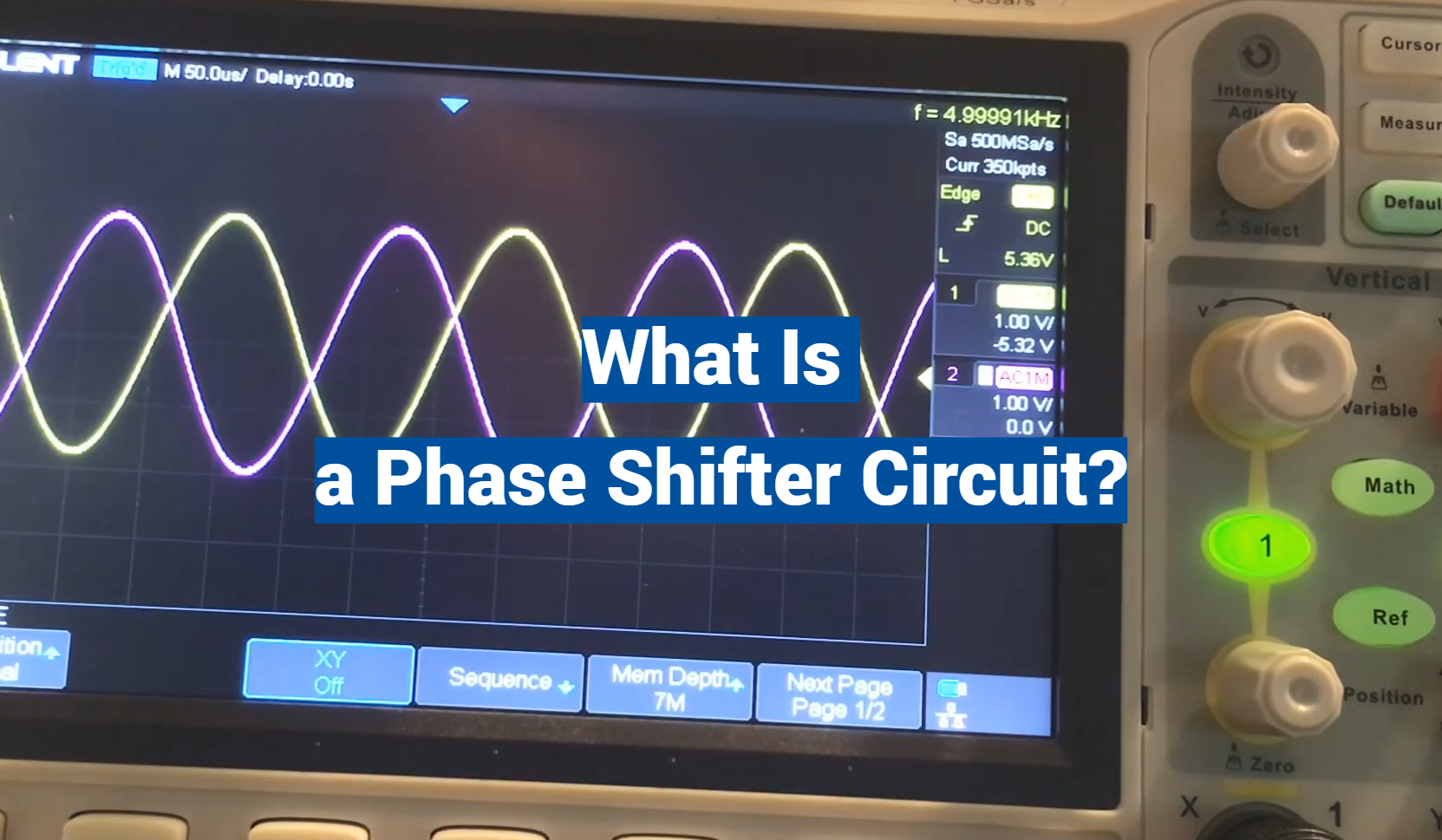
A phase shifter circuit holds a significant place in the realm of electronics, particularly in signal processing and telecommunications. Operating as a crucial component, it shifts or alters the phase angle of a signal, thereby regulating its timing or synchronization. This function is especially critical in radio frequency applications and can greatly influence the quality and efficiency of transmissions.
Basics of Phase Shifter Circuit
How Does it Work?
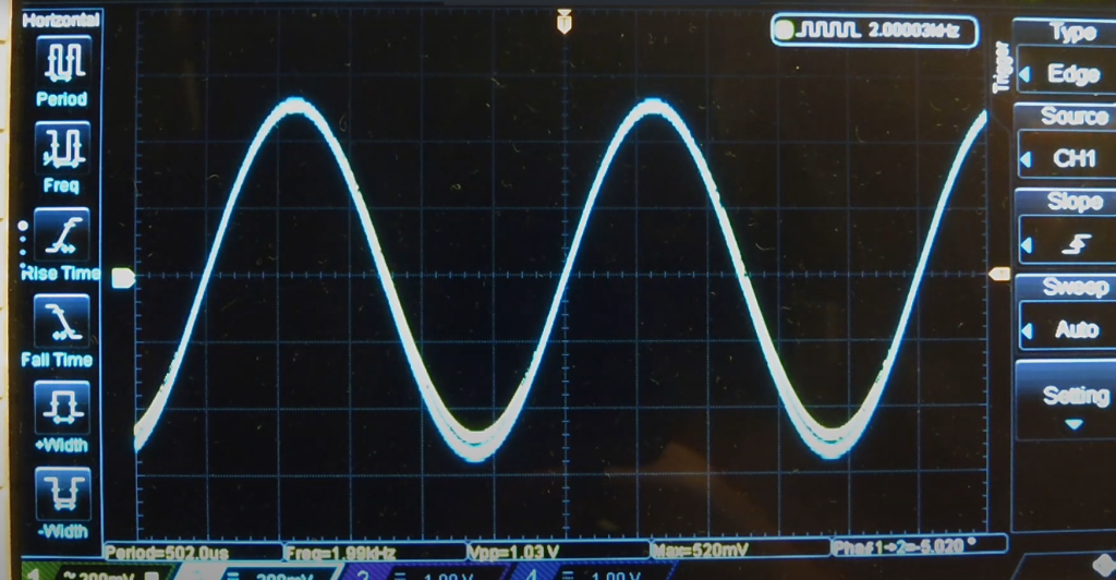
The basic principle behind a phase shifter circuit is the use of reactive components such as capacitors and inductors. These components are able to store and release energy, which makes them useful for manipulating the phase of a signal.
When a signal is passed through a reactive component, it experiences a phase shift. The amount of phase shift depends on the frequency of the signal and the value of the reactive component. By combining different reactive components in a circuit, it is possible to achieve precise control over the phase shift of a signal.
This allows the circuit to manipulate signals in various ways, such as delaying or advancing the phase of a signal.
Types of Phase Shifters
There are different types of phase shifter circuits, each with its own unique characteristics and applications. Some common types include:
- Passive Phase Shifters: These use only passive components such as capacitors and inductors and do not require any external power. They are simple in design and often used for small phase shifts.
- Active Phase Shifters: These use active components such as transistors or operational amplifiers to achieve larger phase shifts. They require an external power source and provide better control over the phase shift.
- Digital Phase Shifters: As the name suggests, these use digital circuitry to achieve precise and discrete phase shifts. They are commonly used in communication systems.
- Analog Phase Shifters: These use analog elements such as potentiometers or variable capacitors to achieve continuous phase shifts. They are often used in audio equipment. [1]
Applications of Phase Shifter Circuits
Phase shifter circuits have various applications in electronic systems, such as:
- Antenna Arrays: In communication systems that use multiple antennas, phase shifters are used to adjust the phase of each antenna and enhance the signal reception.
- Audio Equipment: Phase shifters are commonly used in audio equipment such as guitar pedals or speakers to achieve different sound effects.
- RF Testing: In RF testing, phase shifters are used to manipulate the phase of a signal for various purposes such as calibration or measurement.
- Phase-locked Loops (PLL): Phase shifter circuits are an essential component of PLLs, which are used in communication systems and electronic devices for frequency synthesis and synchronization.
Advantages and Disadvantages of Phase Shifter Circuit
Advantages:
- Precise control over phase shift.
- Can be used in a variety of applications.
- Allows for manipulation of signals without altering their amplitude or frequency.
Disadvantages:
- Sensitive to environmental factors such as temperature and voltage fluctuations.
- Can introduce noise into the signal.
- Complex circuits may be costly and require careful calibration.
Overall, phase shifter circuits play a crucial role in modern electronic systems and have a wide range of applications. With advancements in technology, these circuits continue to evolve and improve, making them an integral part of many industries.
Choosing the Right Phase Shifter Circuit for Your Application
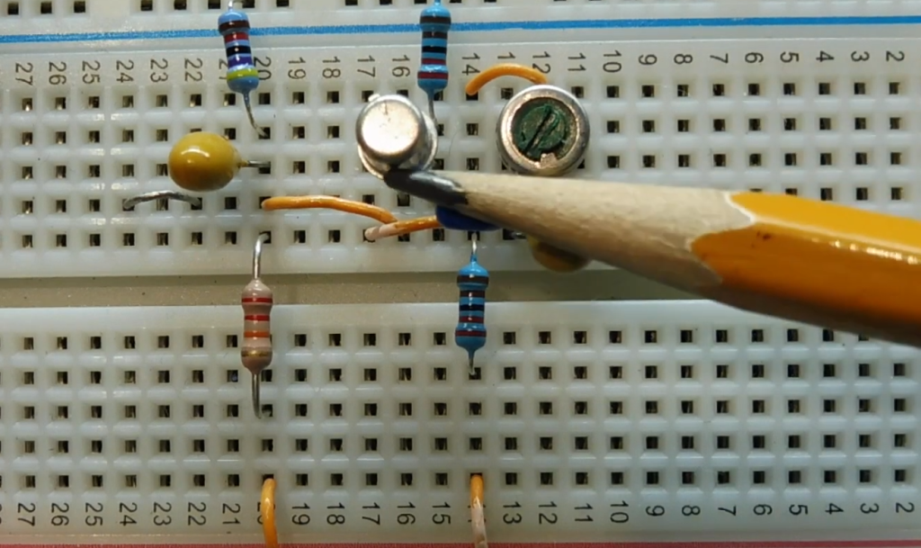
When selecting a phase shifter circuit, it is important to consider factors such as the desired phase shift range, frequency range, and power requirements. Additionally, the type of application and budget should also be taken into account.
It is always recommended to consult with an expert or refer to technical specifications before making a decision. With the right selection and proper implementation, a phase shifter circuit can greatly enhance the performance and functionality of electronic systems. So, it is important to carefully evaluate the options available and choose the one that best suits your specific needs. [2]
Design Considerations for Phase Shifter Circuits
There are several design considerations that should be kept in mind when designing a phase shifter circuit, such as:
- Component Selection: Choosing the right components with appropriate values is crucial for achieving the desired phase shift. The selection of reactive components should also take into account factors such as temperature stability and tolerance.
- Impedance Matching: To avoid signal reflections and ensure efficient transfer of power, the circuit should be designed to match the impedance of the input and output signals.
- Stability: Phase shifter circuits can be sensitive to changes in temperature and voltage. Thus, it is important to design for stability by choosing stable components and using proper shielding techniques.
- Noise Reduction: As phase shifter circuits can introduce noise into the signal, it is important to design for noise reduction by carefully selecting components and implementing proper filtering techniques.
- Calibration: For precise control over the phase shift, it is important to calibrate the circuit properly. This may involve adjusting component values or using trimmer capacitors or inductors.
With these considerations in mind, a well-designed phase shifter circuit can provide accurate and reliable performance in various applications. So, it is important to carefully consider these factors during the design process.
Does Phase Shift Affect Frequency?
When discussing phase shift circuits, one may wonder if phase shift has any effect on frequency. The answer is yes, it does have an impact on frequency.
To understand this better, we need to first define what exactly a phase shifter circuit is. A phase shifter circuit is a type of electronic circuit that can alter the phase of a given signal without changing its amplitude or frequency. This is achieved by using different components such as capacitors, inductors, and resistors.
Now, when a signal goes through a phase shifter circuit, the phase of the output signal will have changed relative to the input signal. This means that the starting point of the waveform has shifted, resulting in a change in the time difference between two signals.
This change in phase can also be interpreted as a delay or advancement of the signal.
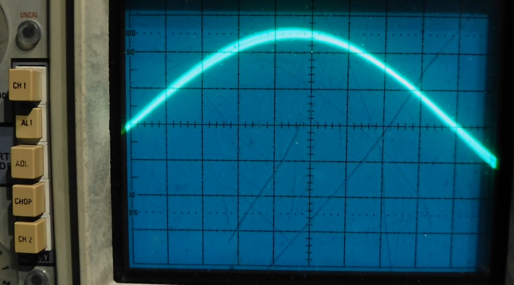
So how does this affect frequency? Well, it all comes down to the relationship between phase and frequency. In simple terms, phase is a measure of how shifted a waveform is compared to its original starting point, while frequency is a measure of how many cycles of the waveform occur in one second.
When a signal is shifted in phase, the number of cycles that occur in one second remains the same, but the starting point may be different. This means that even though the frequency of the signal hasn’t changed, its phase has been altered which can have significant effects on how it behaves in a circuit.
One practical application where this becomes important is in audio engineering. Phase shifts can be used to create different effects in sound production, such as phaser and flanger effects.
In summary, phase shift does indeed affect frequency in a circuit. While the frequency of the signal remains constant, its phase can be changed through the use of phase shifter circuits which ultimately impacts how it behaves in a circuit. This relationship between phase and frequency is also utilized in various applications, making phase shifters an essential component in electronic circuits. So, it is important to understand the concept of phase shifting and its effects on frequency when working with electronic circuits. [3]
Does a Capacitor Cause Phase Shift?
In a phase shifter circuit, capacitors are commonly used components to achieve the desired phase shift. But does the presence of a capacitor automatically cause a phase shift? The answer is no, it depends on how the capacitor is connected in the circuit.
When a capacitor is connected in series with other components such as inductors and resistors, it can cause a phase shift in the output signal. This is because capacitors have the ability to store and release electrical energy, which can change the timing of the signal.
On the other hand, if a capacitor is connected in parallel with other components, it will not cause a phase shift but rather change the amplitude of the signal.
It’s also important to note that different values of capacitance can result in different amounts of phase shift. This is because the amount of charge a capacitor can hold depends on its capacitance value, which in turn affects the timing and phase of the signal.
Overall, while a capacitor itself may not cause a phase shift, its placement and value in a circuit can have significant impacts on the resulting output signal. This highlights the importance of understanding how each component functions in a circuit to achieve desired results. Experimenting with different configurations and values can lead to interesting and useful applications of phase shifting in electronic circuits.
Does Phase Shift Have a Unit?
Phase shift, being a measure of how shifted a waveform is, is typically represented in degrees or radians. This is because phase shift can be measured by the angular difference between two signals.
In terms of units, one cycle of a wave corresponds to 360 degrees or 2π radians. So when talking about phase shift, we may say something like “The signal has a phase shift of 45 degrees” or “The output signal is shifted by π/2 radians”.
It’s important to note that while phase shift itself may not have a unit, the measurement of it does. This distinction is important when discussing phase shifting in technical terms.
Understanding the concept of units and measurements in phase shifting can be helpful in accurately analyzing and designing circuits that incorporate this phenomenon. So, while phase shift may not have a physical unit, its measurement is crucial in the world of electronics and signal processing.
Is Phase Shift Only Horizontal?
When discussing phase shift, one may envision a signal being shifted in a horizontal direction. While this is often the case, it’s important to note that phase shift can also occur in a vertical direction.
In electronic circuits, vertical phase shifting is commonly achieved using op-amps and feedback networks. This allows for precise control of the amplitude and phase of an input signal.
One practical application of vertical phase shifting is in image and video processing. By shifting the phases of different color signals, we can create a variety of visual effects such as color correction and manipulation.
So while horizontal phase shift may be more commonly discussed, it’s important to remember that phase shift can occur in both directions and has various applications in different fields. This showcases the versatility and importance of understanding phase shifting in electronic circuits. [4]
What Is The Difference Between Phaser And Phase Shifter?
Although the terms “phaser” and “phase shifter” are often used interchangeably, they refer to different types of circuits. A phaser is a type of audio effect that modulates the phase of an audio signal to create a sweeping or swirling sound. On the other hand, a phase shifter circuit is primarily used for manipulating signals in communication systems and has a wider range of applications. So while both circuits involve phase shifting, they serve different purposes and have distinct design considerations. Ultimately, the choice between a phaser or phase shifter circuit would depend on the intended application and desired effect.
How Do You Find The Phase Shift Of A Circuit?
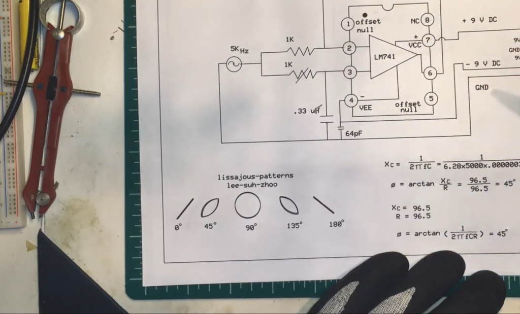
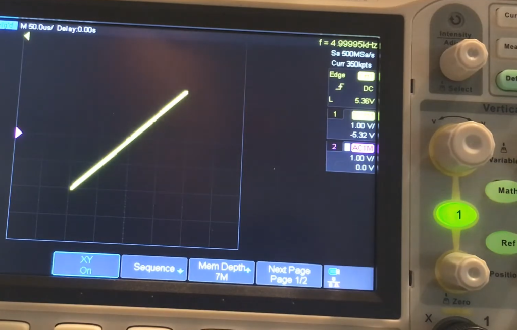
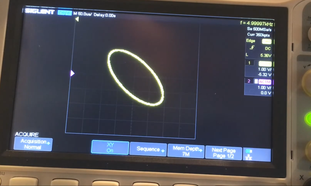
The phase shift of a circuit can be calculated by measuring the difference in phase between the input and output signals. This can be done using an oscilloscope or other signal measurement equipment. The formula for calculating phase shift is given as:
phase shift = (input signal phase – output signal phase) / 360 degrees
Alternatively, if the circuit is designed to provide a specific phase shift, the value can be determined from the component values and circuit design. In some cases, simulation software can also be used to predict and verify the phase shift of a circuit before implementation.
Why Is There Phase Shift In AC Circuits?
Phase shift in AC circuits occurs due to the presence of reactive components such as capacitors and inductors. These components introduce a phase difference between the voltage and current, resulting in a phase shift. In simple terms, this means that the current may reach its peak at a different time than the voltage, leading to a change in the overall phase of the circuit. This phase shift is necessary for certain circuit functions, such as filtering and frequency manipulation.
Can a VFD Be Used As A Phase Converter?
FAQs
What is a Phase Shifter Circuit?
A phase shifter circuit is an electronic device that can adjust the phase of a signal. This means it can change the timing of when a signal reaches its peak or zero point in relation to another signal. Phase shifters are commonly used in communication systems, audio equipment, and other electronic devices.
How does a Phase Shifter Circuit work?
Phase shifters use various components, such as capacitors or inductors, to alter the phase of a signal. The amount of phase shift is determined by the value and configuration of these components. By changing the values or configurations, the timing of the signal can be adjusted.
What are the different types of Phase Shifter Circuits?
There are two main types of phase shifter circuits: analog and digital. Analog phase shifters use passive components, such as capacitors and inductors, to adjust the phase. Digital phase shifters use active components, such as transistors or integrated circuits, to digitally control the phase.
What are the applications of Phase Shifter Circuits?
Phase shifter circuits have many practical uses. In communication systems, they can be used to align signals or cancel out interference. In audio equipment, they can be used to adjust the timing of different frequencies for better sound quality. They are also commonly used in radar systems and medical imaging devices.
What is a Variable Phase Shifter Circuit?
A variable phase shifter circuit allows for continuous adjustment of the phase shift, rather than fixed increments. This can be useful in applications where precise control over the phase of a signal is necessary, such as in antenna arrays or mixer circuits. Variable phase shifter circuits often use voltage-controlled components to achieve this flexibility.
Can Phase Shifter Circuits be used for frequency shifting?
While the main purpose of phase shifter circuits is to adjust the timing of signals, they can also have an impact on the frequency of a signal. This is because changing the phase can also change the wavelength of the signal, effectively shifting its frequency by a certain amount. However, phase shifter circuits are not typically used for this purpose and there are other more specialized circuits designed specifically for frequency shifting.
What factors affect the performance of a Phase Shifter Circuit?
The performance of a phase shifter circuit can be affected by various factors such as temperature, component quality, and signal frequency. Temperature changes can affect the conductivity of components, leading to potential inaccuracies in the phase shift. Poor quality components can also introduce unwanted noise or distortion into the signal. Additionally, different frequencies require different amounts of phase shifting, so the design of the circuit must take this into account for optimal performance.
Are there any limitations of Phase Shifter Circuits?
While phase shifter circuits have many useful applications, they also have some limitations. For example, they can only adjust the phase of a signal within a certain range, beyond which the circuit may not be able to accurately achieve the desired phase shift. Additionally, as with any electronic circuit, there is a limit to how precise the adjustment can be due to factors such as component tolerances and environmental conditions.
What are some common challenges faced in designing and using Phase Shifter Circuits?
Designing and using phase shifter circuits can come with its own set of challenges. One challenge is selecting the appropriate components for the desired phase shift range and accuracy. Another challenge is ensuring that the circuit functions properly in various environmental conditions, as changes in temperature or humidity can affect performance. Additionally, troubleshooting any issues with the circuit can be difficult due to the complex nature of its operation.
What are some current advancements in Phase Shifter Circuit technology?
As technology advances, so do phase shifter circuits. Some current advancements include the development of integrated circuits that can achieve wider ranges and more precise control over the phase shift. There are also efforts to improve the performance of digital phase shifter circuits by reducing noise and distortion. Additionally, there is ongoing research into using novel materials and techniques, such as metamaterials, for more efficient and compact phase shifter circuits.
Conclusion
As we reach the end, it is important to recap some of the key points discussed regarding phase shifter circuits.
Firstly, a phase shifter circuit is an electronic device or module that can adjust the phase shift between input and output signals. This is typically achieved by varying the impedance of a component within the circuit.
Phase shifters have numerous applications in various industries, such as telecommunications, radar technology, and audio engineering. They are particularly useful in applications where precise control of phase shifts is necessary.
There are several types of phase shifter circuits, including analog and digital phase shifters. Analog phase shifters utilize variable capacitors or inductors to vary the impedance, while digital phase shifters use electronic switching elements.
Additionally, phase shifters can also be categorized based on the type of phase shift they produce. These include fixed, variable, and continuously tunable phase shifters.
It is important to note that the choice of phase shifter circuit depends on the specific application and its requirements. Therefore, it is essential to carefully consider factors such as frequency range, resolution, insertion loss, and size when selecting a phase shifter circuit.
In conclusion, phase shifter circuits play a crucial role in various industries, providing precise control of phase shifts for a wide range of applications. With advancements in technology, we can expect to see even more sophisticated and efficient phase shifter circuits in the future. So if you are interested in electronics and signal processing, learning about phase shifter circuits is definitely worth your while. Keep exploring and learning, as there is always more to discover in this exciting field of study!
Useful Video: phase shifter
References:
- https://www.qsl.net/va3iul/Phase_Shifters/Phase_Shifters.pdf
- https://circuitcellar.com/research-design-hub/frequency-independent-phase-shifter/
- http://www.tedpavlic.com/teaching/osu/ece209/lab1_intro/lab1_intro_phase_shifter.pdf
- https://www.allthescience.org/what-is-a-phase-shifter.htm
- https://www.allaboutcircuits.com/technical-articles/understanding-phase-shift-in-analog-circuits/

