The world of electronics offers a fascinating nexus of possibilities, and one such intersection is the interfacing between Arduino and RS485. This article delves into the intricate process of connecting these two technologies. RS485, an asynchronous serial communication protocol, provides balanced performance for long-distance transmission of data.
It’s widely recognized for its reliability and stability. Arduino, on the other hand, is a popular open-source platform used for building electronics projects. Together, they can create powerful systems capable of transmitting data up to 4000 meters.
This introduction sets the stage for a detailed exploration of how to interface Arduino with RS485.
What Is Modbus Protocol?
Here are some key aspects of the Modbus protocol:
- Serial and Ethernet Versions: Modbus is available in both serial (RS-232, RS-485) and Ethernet (TCP/IP) versions. The serial version is often used for connecting devices like programmable logic controllers (PLCs), sensors, and actuators, while the Ethernet version is used for more modern and high-speed industrial networks;
- Master-Slave Communication: Modbus follows a master-slave communication model. A master device, such as a PLC or a computer, initiates communication with one or more slave devices, which can be sensors, drives, or other control devices. The master device sends requests, and the slave devices respond with data or perform actions based on those requests;
- Request-Response Protocol: Communication in Modbus is based on a request-response mechanism. The master sends a request to a specific slave device, specifying the type of operation (e.g., read data, write data), the address of the data, and other relevant information. The slave device processes the request and responds with the requested data or an acknowledgment of the action taken;
- Data Formats: Modbus supports various data formats, including binary, hexadecimal, integer, and floating-point representations. This flexibility allows it to handle different types of data, making it suitable for diverse industrial applications;
- Function Codes: Modbus uses function codes to define the type of operation to be performed. Common function codes include 01 (Read Coil Status), 02 (Read Input Status), 03 (Read Holding Registers), and 16 (Write Multiple Registers). Each function code corresponds to a specific operation;
- Addressing: Modbus devices are typically assigned unique addresses that the master uses to identify and communicate with them. In the case of Modbus TCP/IP over Ethernet, IP addresses and port numbers are used for addressing;
- Error Handling: Modbus includes error-checking mechanisms to ensure data integrity during transmission. If an error occurs, the protocol provides error codes to help diagnose and resolve issues;
- Open Standard: Modbus is an open standard, which means that the protocol specifications are publicly available. This openness has contributed to its widespread adoption and compatibility among different manufacturers’ devices;
- Applications: Modbus is commonly used in industrial automation, including manufacturing, energy management, building automation, and more. It allows different devices from various manufacturers to communicate and work together within a control system [2];
What Is RS485:
RS-485, also known as TIA-485 or EIA-485, is a widely used communication standard in various industrial and commercial applications. It provides a balanced differential signaling method for transmitting data over long distances, making it suitable for environments where noise immunity and robustness are critical.
Topology
RS-485 supports multiple topologies for connecting devices, allowing flexibility in network design.
The most common topologies include:
- Point-to-Point: In a point-to-point configuration, two devices are directly connected using an RS-485 link. This simple setup is ideal for communication between two devices without the need for a network;
- Multi-Drop: In a multi-drop configuration, multiple devices are connected to a single RS-485 bus. Each device has a unique address, and communication occurs one device at a time. This topology is suitable for applications where several devices share the same communication line;
- Daisy Chain: In a daisy chain topology, devices are connected in a linear fashion, forming a chain. Data flows from one device to the next, and termination resistors are required at both ends to prevent signal reflections. Daisy chain setups are common in long-haul RS-485 networks;
Signaling
RS-485 uses differential signaling, which means it transmits data as a voltage difference between two wires: A (positive) and B (negative).
Key characteristics of RS-485 signaling include:
1. Differential Voltage Levels:
Logic “1” is represented by a higher voltage on wire A compared to wire B, and logic “0” is the opposite.
This differential signaling minimizes the impact of electromagnetic interference (EMI) and common-mode noise.
2. Noise Immunity:
RS-485’s balanced signaling makes it immune to common-mode noise, such as voltage spikes and electromagnetic interference. This feature is crucial in industrial environments with electrical noise [3].
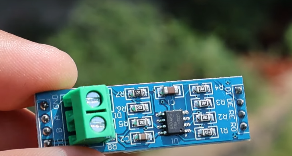
Transceiver Design
The RS-485 transceiver is a critical component that interfaces with the communication bus. It includes:
- Driver and Receiver: The driver sends data onto the bus, while the receiver interprets incoming data. These components must handle differential signaling and ensure data integrity;
- Half-Duplex Operation: RS-485 is typically half-duplex, meaning devices can either transmit or receive data at any given time. This simplicity in operation contributes to the robustness of the standard;
Data Transmission
RS-485 data transmission involves several aspects:
- Baud Rate and Data Rate: The baud rate determines the speed of data transmission. RS-485 supports various baud rates, allowing flexibility to balance speed and reliability;
- Frame Format: Data is transmitted in frames, which include start and stop bits, data bits, and optional parity bits. Common formats are 8-N-1 (8 data bits, no parity, 1 stop bit) and 9-N-1 (8 data bits, 1 parity bit, 1 stop bit);
- Synchronization: Devices on the RS-485 network must agree on the frame format and timing for proper communication;
SC & Ground Connection
Proper grounding and common signal (SC) connections are essential for RS-485 networks:
- Signal Common (SC): SC is a reference point for the differential signaling, ensuring that both the A and B wires are measured relative to a common ground;
- Grounding: Grounding practices, such as star grounding or single-point grounding, help minimize ground loop issues and maintain signal integrity;
The Communication Protocol of RS-485
RS-485 defines the physical layer for communication but leaves the choice of communication protocol to the users.
Commonly used communication protocols on RS-485 networks include:
- Modbus: Modbus is a widely adopted protocol for industrial automation and control systems. It uses a master-slave architecture and is known for its simplicity and versatility;
- Profibus: Profibus is used in industrial automation and process control. It supports various communication speeds and device types;
- DMX512: DMX512 is a lighting control protocol used in entertainment and architectural lighting systems. It is designed for controlling lighting fixtures and dimmers;
RS-485 and Arduino
The Arduino platform has gained popularity in industrial and automation projects due to its flexibility and ease of use.
Integrating RS-485 with Arduino can be advantageous for various applications:
- Hardware Compatibility: Arduino boards can be equipped with RS-485 communication modules or shields, making it easy to connect to RS-485 networks;
- Software Libraries: Arduino supports several RS-485 libraries that simplify communication setup and data exchange with RS-485 devices;
- Industrial Automation: Arduino can serve as a low-cost controller in industrial automation setups, interfacing with sensors, actuators, and other equipment via RS-485;
Reading RS-485 Data Using Arduino
To read data from an RS-485 network using Arduino, you’ll need to follow these steps:
- Hardware Setup: Connect the RS-485 transceiver module to your Arduino board, ensuring proper wiring for data, power, and ground;
- Install RS-485 Library: Install the necessary RS-485 communication library for Arduino. Libraries like “ModbusMaster” or “SimpleModbus” are commonly used;
- Configure Communication Parameters: Set the appropriate baud rate, data format, and RS-485 transceiver control pins in your Arduino code;
- Read Data: Implement code to send requests and receive responses from RS-485 devices. Depending on your application and protocol, you may need to parse and process the received data;
- Data Display or Control: Use the data obtained from the RS-485 network to display information on an Arduino LCD, control relays, or perform any desired actions [4];
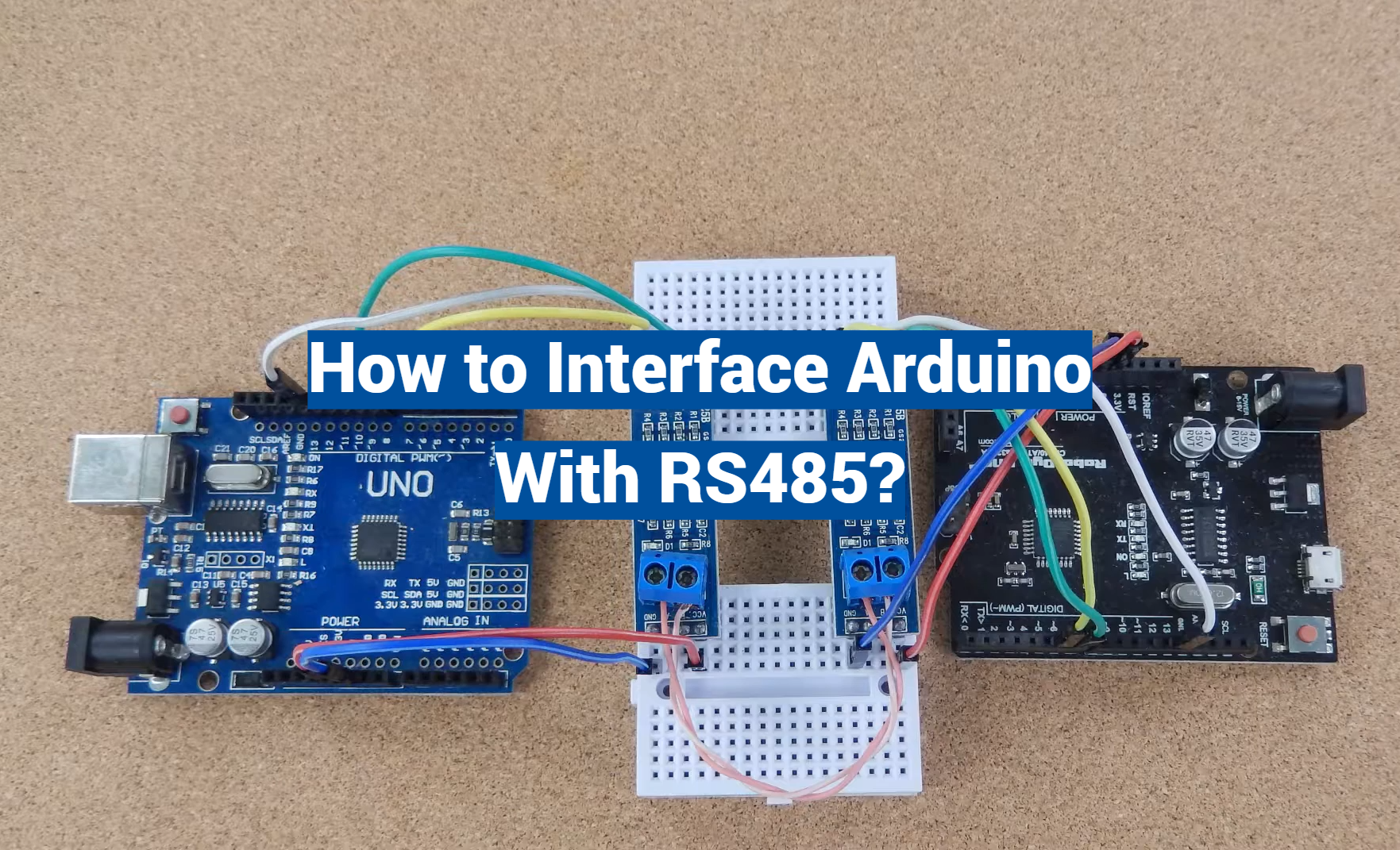
RS485 Serial Communication Between Two Arduino Boards:
Serial communication between two Arduino boards using the RS485 protocol is a common scenario in various projects, especially in industrial automation and remote monitoring applications.
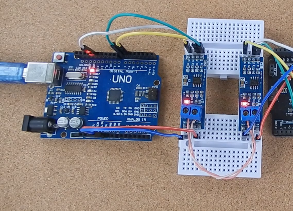
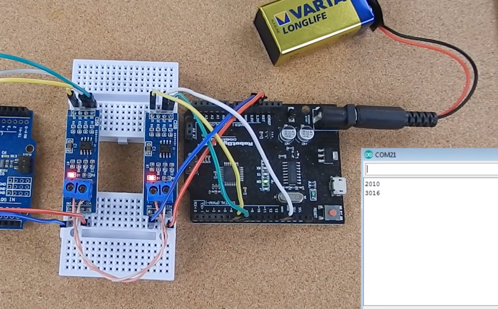
Master and Slave Configuration Circuit Diagram
Before diving into the code, let’s set up the hardware connection between the two Arduino boards.
Here’s a circuit diagram for the master and slave configuration:
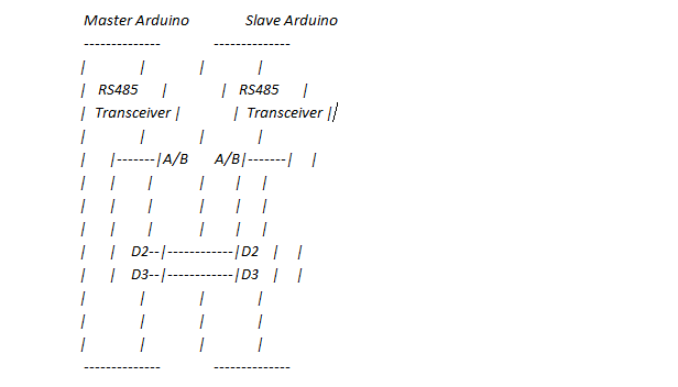
In this diagram:
- Both the master and slave Arduino boards are connected to an RS485 transceiver module with A (positive) and B (negative) connections;
- The A and B pins on the transceiver modules are connected to digital pins 2 and 3 on both Arduino boards;
- Make sure to connect the ground (GND) of both Arduino boards to establish a common ground reference;
Installing OLED Libraries in Arduino IDE
If you plan to use an OLED display to visualize data on either the master or slave Arduino, you need to install the necessary libraries in the Arduino IDE.
To install libraries in the Arduino IDE, follow these steps:
- Open the Arduino IDE;
- Go to “Sketch” -> “Include Library” -> “Manage Libraries…”;
- In the Library Manager, you can search for and install libraries related to your OLED display (e.g., “Adafruit SSD1306” for OLED displays using the SSD1306 driver) [5];
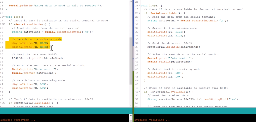
Arduino Sketch for Master: Code
Now, let’s write the Arduino sketch (code) for the master Arduino board. This code will send data to the slave Arduino and display information on an OLED display (if connected).
#include <SoftwareSerial.h>
#include <Wire.h>
#include <Adafruit_GFX.h>
#include <Adafruit_SSD1306.h>
#define OLED_RESET -1 // Reset pin (or -1 if you don’t need to reset)
Adafruit_SSD1306 display(OLED_RESET);
SoftwareSerial rs485(2, 3); // RX, TX pins for RS485 communication
void setup() {
rs485.begin(9600); // Set the baud rate for RS485 communication
Serial.begin(9600); // Set the baud rate for serial monitor
display.begin(SSD1306_I2C_ADDRESS, SSD1306_I2C_SDA, SSD1306_I2C_SCL);
// Initialize the OLED display
if(!display.begin(SSD1306_I2C_ADDRESS, SSD1306_I2C_SDA, SSD1306_I2C_SCL)) {
Serial.println(F(“SSD1306 allocation failed”));
for(;;);
}
display.display(); // Display initialization
delay(2000); // Pause for 2 seconds
display.clearDisplay();
display.setTextSize(1);
display.setTextColor(SSD1306_WHITE);
display.setCursor(0,0);
display.print(F(“Master Arduino”));
display.display();
delay(2000); // Pause for 2 seconds
display.clearDisplay();
}
void loop() {
String dataToSend = “Hello, Slave!”; // Data to send
rs485.println(dataToSend); // Send data to the slave
delay(1000); // Send data every 1 second
// Add more code here.
}
This code initializes communication over RS485, sends data to the slave Arduino, and displays information on the OLED display.
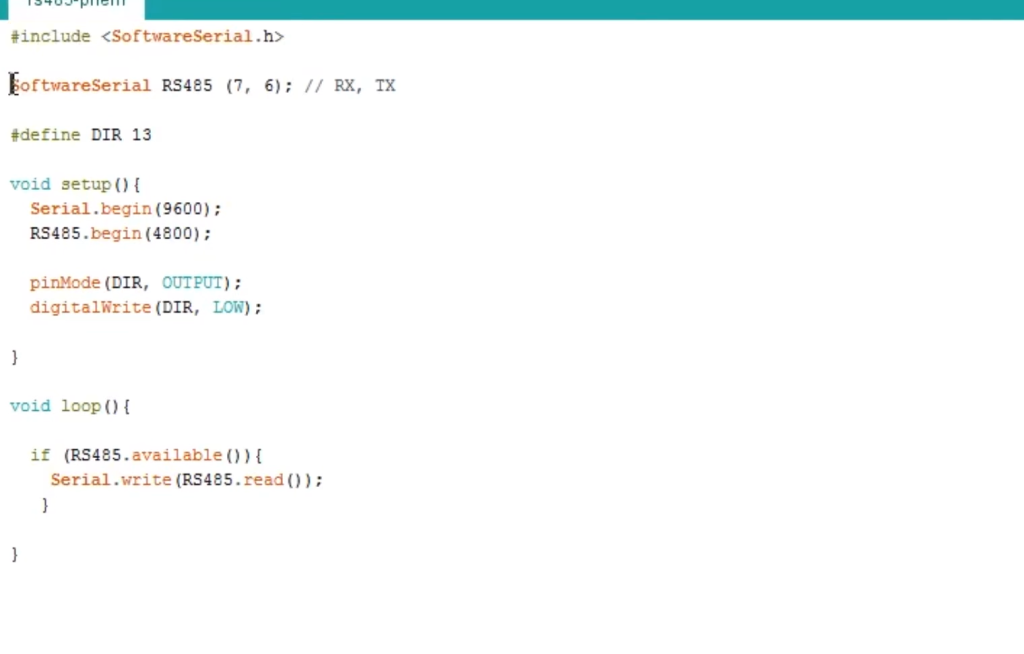
Arduino Sketch for Slave: Code
Next, let’s write the Arduino sketch (code) for the slave Arduino board. This code will receive data from the master Arduino over RS485 and display it on the serial monitor.
#include <SoftwareSerial.h>
SoftwareSerial rs485(2, 3); // RX, TX pins for RS485 communication
void setup() {
rs485.begin(9600); // Set the baud rate for RS485 communication
Serial.begin(9600); // Set the baud rate for serial monitor
}
void loop() {
if (rs485.available()) {
String receivedData = rs485.readStringUntil(‘\n’); // Read data from master until newline character
Serial.print(“Received data from master: “);
Serial.println(receivedData);
// You can add more code here to process received data or perform other tasks.
}
}
This code initializes RS485 communication on the slave Arduino, listens for incoming data from the master, and prints received data on the serial monitor [6].
FAQ:
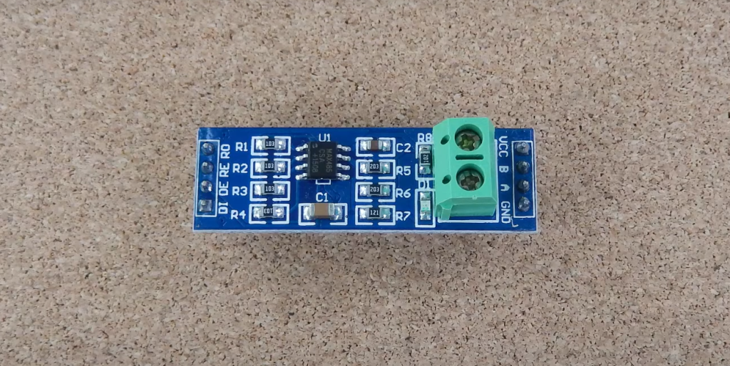
1. How to Connect RS485 to Arduino?
To connect RS485 to an Arduino, follow these steps:
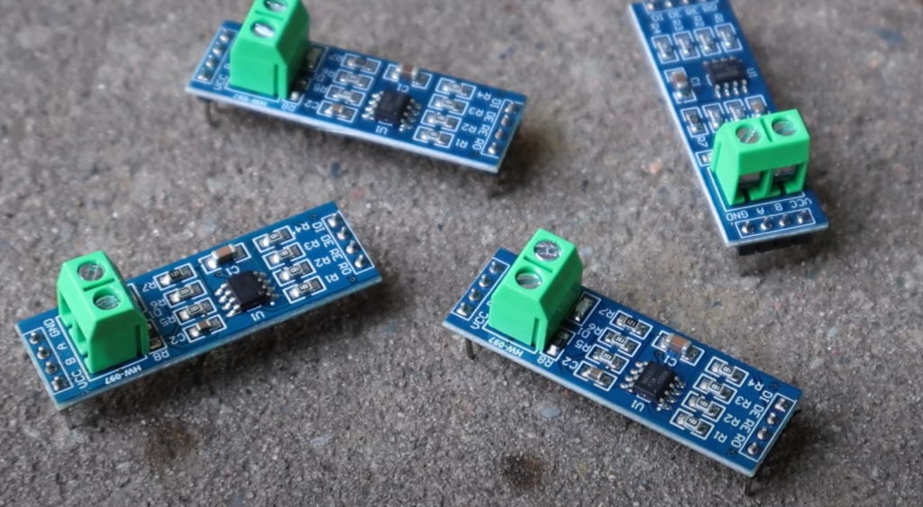
Choose an RS485 Transceiver: Select an RS485 transceiver module or chip compatible with your Arduino board. These modules typically have A (positive) and B (negative) connections for the RS485 communication lines.
Connect the RS485 Module to Arduino:
- Connect the A (positive) and B (negative) pins of the RS485 module to the digital pins on your Arduino. Common choices are digital pins 2 and 3;
- Connect the ground (GND) of the RS485 module to the Arduino’s ground (GND) to establish a common ground reference;
- Power Supply: Ensure that the RS485 module is powered appropriately. Most RS485 modules operate with a 5V supply, so make sure the voltage matches your Arduino’s operating voltage;
- Termination Resistor (Optional): For long-distance communication or in cases of signal reflection, you may need termination resistors (typically 120-220 ohms) at both ends of the RS485 bus;
- Program Arduino: Write and upload Arduino code to initiate and manage RS485 communication [7];
2. Is RS485 Compatible with Arduino?
Yes, RS485 is compatible with Arduino. Arduino boards can be interfaced with RS485 transceiver modules or chips, allowing them to communicate using the RS485 protocol. Arduino libraries and examples are available to facilitate RS485 communication.
3. How to Connect RS485 to a Microcontroller?
Connecting RS485 to a microcontroller, including an Arduino, involves similar steps as mentioned earlier. You need an RS485 transceiver module or chip compatible with your microcontroller. Connect the A and B lines to the microcontroller’s digital pins, establish a common ground, and ensure a suitable power supply. Then, program the microcontroller to send and receive data over the RS485 bus.
4. Is RS485 the Same as a CAN Bus?
No, RS485 and the CAN (Controller Area Network) bus are not the same.
While both are communication protocols used in industrial and automotive applications, they have distinct characteristics:
- RS485 is a point-to-point or multi-point communication protocol often used for longer-distance communication in industrial settings. It typically employs a master-slave or multi-drop configuration;
- CAN bus is a multi-master, multi-drop protocol used for communication between electronic control units (ECUs) in vehicles and other applications. It offers higher-speed communication and built-in error handling;
5. Can I Use RS485 Instead of RS232?
Yes, you can use RS485 instead of RS232 in many applications, but there are some important considerations:
RS232 is a point-to-point communication protocol, typically used for short-distance serial communication (up to 15 meters). It uses voltage levels around ±12V [8].
RS485 is suitable for longer-distance communication (up to thousands of meters) and can support multi-point or multi-drop configurations. It uses differential signaling (A and B lines) for noise immunity. To replace RS232 with RS485, you may need an RS485 transceiver and proper wiring adjustments.
6. Is RS485 a UART?
RS485 and UART (Universal Asynchronous Receiver-Transmitter) are related but not the same. UART is a hardware component or communication protocol commonly found in microcontrollers and communication chips. It manages the serial data format and timing.
RS485, on the other hand, is a physical layer and electrical specification that defines how data is transmitted over a communication medium, such as twisted-pair wires. You can use UART to communicate data over RS485 by connecting the UART interface to an RS485 transceiver.
7. What Voltage Input for RS485?
RS485 typically operates with a voltage range between 4.75V and 5.25V for a standard 5V system. The exact voltage level may vary depending on the specific RS485 transceiver module or chip used. It’s important to ensure that the RS485 module’s power supply voltage matches the voltage level of your system.
8. Does RS485 Need 5V?
RS485 modules are commonly designed to work with a 5V power supply and logic level. However, RS485 transceivers with lower voltage support (e.g., 3.3V) are available for systems with different voltage requirements. Always check the datasheet of your RS485 transceiver to confirm its voltage compatibility with your system.
9. How to Use RS485 Communication?
Using RS485 communication involves several steps:
- Connect RS485 transceivers to the devices you want to communicate with;
- Wire the A and B lines of the RS485 transceivers to your communication devices;
- Establish a common ground between all devices;
- Power the RS485 modules and devices
- Configure communication settings like baud rate and frame format
- Write code on your microcontroller or computer to send and receive data via RS485;
- Implement a communication protocol if necessary to ensure proper data exchange;
10. Does Modbus Use RS485?
Yes, Modbus is a communication protocol that often uses RS485 as its physical layer for data transmission. Modbus is widely used in industrial automation and control systems, and RS485 is a popular choice for its robustness in these environments.
11. Is Modbus TCP RS485?
No, Modbus TCP and RS485 are different communication methods:
Modbus TCP is a Modbus variant that runs over Ethernet networks using TCP/IP as the transport protocol. It uses Ethernet cables and is commonly used for communication between devices on Ethernet networks.
RS485 is a physical layer and electrical specification that defines how data is transmitted over twisted-pair wires. It is often used for communication over long distances in industrial settings.
12. Is RS485 the Same as Ethernet?
No, RS485 and Ethernet are different communication technologies:
- RS485 is a serial communication standard used for point-to-point or multi-point communication over twisted-pair wires. It is common in industrial applications;
- Ethernet is a network communication standard used for data exchange in local area networks (LANs) and wide area networks (WANs). It uses Ethernet cables and typically operates at higher data rates;
13. Is RS485 2 Wire or 4 Wire?
RS485 communication can be implemented with either 2 wires or 4 wires, depending on the specific application and requirements:
- 2-Wire RS485: This is the most common configuration and uses one twisted-pair cable for both transmission and reception. It’s suitable for point-to-point and multi-point communication;
- 4-Wire RS485: In this configuration, two separate twisted-pair cables are used, one for transmission (A and A’) and one for reception (B and B’). It is often used for high-noise environments to further isolate the transmit and receive paths;
14. Does RS485 need a resistor?
In some cases, RS485 communication may benefit from termination resistors. Termination resistors (typically 120-220 ohms) are added at both ends of the RS485 bus to reduce signal reflections and improve signal integrity, especially in long-distance or high-speed communication. The need for termination resistors depends on the specific RS485 network and its electrical characteristics.
15. Does RS485 require ground?
Yes, RS485 communication typically requires a common ground reference between all devices on the network. Establishing a common ground helps ensure proper voltage level referencing and reliable communication. It is essential to connect the ground (GND) of all RS485 devices to a common ground point.
16. Does USB Use RS485?
No, USB (Universal Serial Bus) and RS485 are distinct communication standards. USB is a common interface for connecting various peripherals to computers and other devices, while RS485 is a protocol used for serial data communication over longer distances in industrial and commercial applications. They use different physical connectors, protocols, and signaling methods.
17. Is RS485 Parallel or Series?
RS485 is a serial communication protocol, meaning it transmits data one bit at a time over a single pair of wires (A and B) in a sequential fashion. It is not parallel communication, which involves transmitting multiple bits simultaneously over multiple wires. RS485 can be used in both point-to-point and multi-point configurations for serial data transmission.
Useful Video: How to interface RS485 with Arduino
References:
- https://embeddedthere.com/how-to-interface-arduino-with-rs485-modbus-protocol-using-max485-module/
- https://docs.arduino.cc/tutorials/opta/getting-started-with-rs485
- https://www.hackster.io/maurizfa-13216008-arthur-jogy-13216037-agha-maretha-13216095/modbus-rs-485-using-arduino-c055b5
- https://www.circuitstate.com/tutorials/what-is-rs-485-how-to-use-max485-with-arduino-for-reliable-long-distance-serial-communication/
- https://microcontrollerslab.com/rs485-serial-communication-arduino-tutorial/
- https://www.engineersgarage.com/rs485-communication-between-arduino-mega-and-arduino-pro-mini/
- https://microdigisoft.com/rs-485-serial-communication-between-two-arduino/
- https://handtoolsforfun.com/how-to-read-rs485-data-using-arduino/