In this comprehensive guide, we delve into the world of Arduino OPTA programming. Arduino OPTA (Opta), a versatile and powerful mini PLC platform, offers a plethora of programming opportunities for tech enthusiasts and professionals alike. Whether you’re looking to use the classic Arduino IDE or the more specialized Arduino PLC IDE, this article aims to provide you with clear, step-by-step instructions.
From initial setup to downloading your first program, we cover it all. This article is perfect for programmers who are just starting out with Arduino Opta or those who are looking to expand their skills.
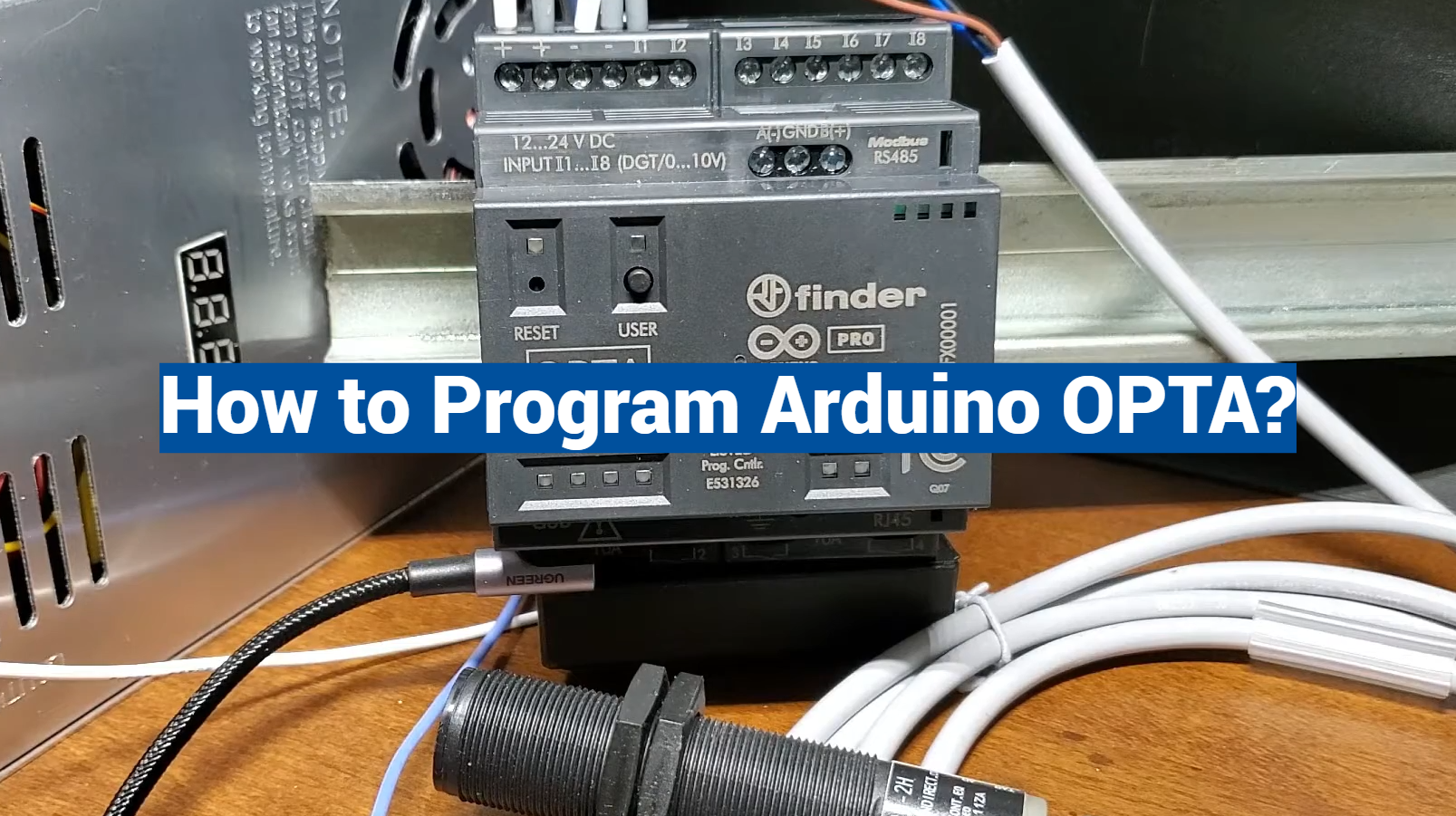
Arduino OPTA WiFi Micro PLC
Automation has become an integral part of our daily lives, enhancing efficiency and precision across various industries. Arduino, a household name in the world of electronics and programming, has taken a significant step forward in the realm of automation with the Arduino OPTA WiFi Micro PLC [1].
Specifications
The Arduino OPTA WiFi Micro PLC boasts an impressive set of specifications that make it a compelling choice for automation enthusiasts and professionals alike:
1. Processor and Memory:
- Microcontroller: ATmega4809;
- Flash Memory: 48KB;
- RAM: 6KB;
- Clock Speed: 20MHz;
2. Communication:
- WiFi: ESP32-WROOM-32E module;
- Ethernet: RJ45 connector for wired connectivity;
- USB: USB-C for programming and debugging;
3. Inputs and Outputs:
- Digital Inputs: 8;
- Analog Inputs: 4;
- Relay Outputs: 4;
- PWM Outputs: 4;
4. Power Supply
- Input Voltage: 12-24V DC;
- Power Consumption: < 2W;
5. Dimensions:
- Size: 100mm x 75mm;
- Mounting: DIN rail or wall mounting;
6. Operating Temperature:
- -20°C to 70°C;
7. Programming:
- Arduino IDE compatible
- Support for ladder logic programming with the Arduino Industrial PLC library
Applications
The Arduino OPTA WiFi Micro PLC finds its applications across a wide spectrum of industries and use cases due to its versatility and compact design [2].
Some prominent applications include:
1. Home Automation:
- Control and monitor lighting, heating, and security systems remotely;
- Integrate with IoT devices for smart home automation;
- Create custom home automation solutions using the Arduino IDE;
2. Industrial Automation:
- Automate machinery and processes in manufacturing plants;
- Monitor and control sensors and actuators in real timereal time;
- Implement custom automation logic with ladder logic programming;
3. Building Management Systems:
- Manage HVAC systems, lighting, and access control;
- Optimize energy usage for sustainability;
- Receive real-time alerts for maintenance and security;
4. Agriculture:
- Monitor and control irrigation systems;
- Collect and analyze environmental data for precision agriculture
- Automate feeding and ventilation systems in poultry farms;
5. Education and Prototyping:
- Ideal for teaching automation and control systems;
- Rapid prototyping of automation projects;
- Learn programming and automation concepts using the Arduino platform;
Pros:
- Compact Design. The small form factor of this micro PLC allows it to fit seamlessly into tight spaces, making it ideal for various applications;
- Connectivity Options. With built-in WiFi and Ethernet connectivity, it’s easy to integrate the device into existing networks and control systems;
- Easy Programming. Arduino’s user-friendly IDE and ladder logic support simplify programming and customization for users of all skill levels;
- Versatile I/O Options. The combination of digital, analog, relay, and PWM outputs provides flexibility for a wide range of automation tasks;
- Real-time Monitoring. Access real-time data and control automation processes remotely, enhancing convenience and efficiency;
- Cost-Effective. Compared to traditional PLCs, the Arduino OPTA WiFi Micro PLC offers a cost-effective solution without compromising on functionality;
Cons:
- Limited Processing Power. The microcontroller’s processing power may be insufficient for highly complex and resource-intensive automation tasks;
- Industrial Durability. While suitable for many industrial applications, it may not withstand extreme conditions and rigorous industrial environments;
- Limited I/O Count. For large-scale automation projects, the limited number of inputs and outputs may require additional expansion modules;
Arduino OPTA Inputs
Understanding the inputs of the Arduino OPTA WiFi Micro PLC is crucial for designing effective automation systems.
This device provides various types of inputs, including:
1. Digital Inputs
The Arduino OPTA features 8 digital inputs, which can be used to read binary signals such as switches, sensors, and limit switches. These inputs are ideal for detecting the state of on/off devices [3].
2. Analog Inputs
With 4 analog inputs, this micro PLC can read continuous voltage levels, allowing you to interface with analog sensors like temperature sensors, pressure transducers, and potentiometers. These inputs enable precise data acquisition.
3. Communication Inputs
Utilizing the built-in WiFi and Ethernet capabilities, the device can receive data and commands from external sources, including mobile applications and web services. This opens up possibilities for remote control and monitoring.
4. Timers and Counters
The device features hardware timers and counters, allowing users to measure time intervals and count external events accurately. This is particularly valuable in applications requiring precise timing and control.
Arduino OPTA Outputs
The outputs of the Arduino OPTA WiFi Micro PLC play a crucial role in controlling external devices and processes.
Here are the primary output types:
1. Relay Outputs
The device offers 4 relay outputs, making it suitable for tasks that require switching high-voltage or high-current loads. Relays are commonly used in industrial applications for controlling motors, pumps, and solenoids.
2. PWM Outputs
Four PWM (Pulse Width Modulation) outputs are available, enabling precise control of devices such as motors and valves. PWM signals are used to regulate the speed and position of various actuators.
3. Digital Outputs
While primarily designed for switching purposes, the digital outputs can also be used for tasks like LED control or signaling. They are versatile and capable of driving a variety of devices.
4. Communication Outputs
The Arduino OPTA WiFi Micro PLC can transmit data and status information via WiFi and Ethernet, allowing it to communicate with other devices, control systems, or cloud platforms [4].
Getting Started with OPTA:
The Arduino OPTA WiFi Micro PLC is a versatile and compact device that enables you to automate various tasks and projects. Whether you’re a beginner or an experienced developer, this guide will walk you through the essential steps to set up and start using your OPTA PLC.
1) Setup with the Arduino IDE
Before you begin, make sure you have the following:
- An Arduino OPTA WiFi Micro PLC;
- A USB-C cable;
- A computer with the Arduino IDE installed;
Here’s how to set up your OPTA with the Arduino IDE:
- Install the Arduino IDE: If you haven’t already, download and install the Arduino IDE from the official Arduino website;
- Connect Your OPTA: Use the USB-C cable to connect your OPTA PLC to your computer. Ensure that your PLC is powered on;
Install the Arduino Board Manager:
- Open the Arduino IDE;
- Go to “File” > “Preferences”
- In the “Additional Boards Manager URLs” field, enter the following URL: https://dl.espressif.com/dl/package_esp32_index.json ;
- Click “OK”;
Install ESP32 Boards:
- Go to “Tools” > “Board” > “Boards Manager…”;
- In the Boards Manager, search for “esp32” and install the “esp32” board package by Espressif Systems;
Select Your Board:
- Go to “Tools” > “Board” and select “Arduino WiFi Micro PLC”;
- Select Your COM Port: Go to “Tools” > “Port” and select the COM port associated with your OPTA PLC;
Now, you’re ready to start programming your OPTA with the Arduino IDE [5].
2) Testing with Blink Sketch:
- Open the Blink Example Sketch: Go to “File” > “Examples” > “01.Basics” > “Blink”;
- Modify the LED Pin: In the Blink sketch, the LED is usually connected to pin 13. Since the OPTA PLC uses different pins, change the LED pin number to the appropriate one. For example, if you’re using pin 4, modify the line:
int led = 13;
to
int led = 4;
- Upload the Sketch: Click the “Upload” button (right-arrow icon) in the Arduino IDE to compile and upload the sketch to your OPTA PLC;
- Observe the LED: After a successful upload, you should see the LED on your OPTA board blink on and off at the specified interval (default is 1 second);
3) Configuring the Programmable Button on the OPTA:
Install the Required Libraries:
- Go to “Sketch” > “Include Library” > “Manage Libraries…”;
- Search for and install the “Blynk” library;
Open the Button Example Sketch:
Go to “File” > “Examples” > “Blynk” > “Button”.
Modify Your Auth Token:
Replace your_auth_token with your Blynk authentication token, which you can obtain by creating a Blynk account and project.
Upload the Sketch:
Click the “Upload” button in the Arduino IDE to upload the modified sketch to your OPTA PLC.
Connect to Blynk App:
- Download the Blynk app on your smartphone and set up a project;
- Connect your OPTA to the Blynk project by entering your Auth Token in the Arduino sketch;
Now, you can use the programmable button on your OPTA to trigger actions in your Blynk project.
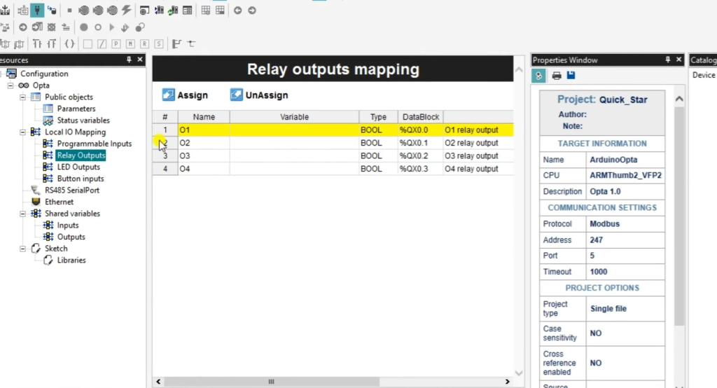
4) Using Output Relays of OPTA
The OPTA PLC includes relay outputs that can control external devices such as motors, lights, or pumps.
To use these outputs:
- Connect Your External Device: Ensure that your external device is connected to one of the relay outputs on the OPTA PLC;
- Write a Sketch: Write an Arduino sketch that controls the relay. For example, you can use the digitalWrite function to turn the relay output on or off;
- Upload the Sketch: Upload the sketch to your OPTA PLC;
The relay should now control your external device based on the instructions in your sketch.
5) Using OPTA PLC’s Inputs
The OPTA PLC also features digital and analog inputs for reading data from sensors or switches.
To use these inputs:
- Connect Your Sensor or Switch: Connect your sensor or switch to one of the digital or analog input pins on the OPTA PLC;
- Write a Sketch: Write an Arduino sketch that reads data from the input pin. Use functions like digitalRead or analogRead to retrieve data from the connected sensor or switch;
- Upload the Sketch: Upload the sketch to your OPTA PLC;
Your OPTA PLC should now be able to gather data from the connected input device.
6) Connecting OPTA to the Cloud
The OPTA PLC supports cloud connectivity, allowing you to monitor and control it remotely. To connect your OPTA PLC to the cloud:
7) Install the Required Libraries:
- Go to “Sketch” > “Include Library” > “Manage Libraries…”;
- Search for and install any libraries required for your cloud platform (e.g., MQTT or Blynk);
- Write a Cloud-Enabled Sketch: Create an Arduino sketch that includes the necessary code to connect to your chosen cloud platform. This may involve setting up Wi-Fi credentials, configuring MQTT settings, or integrating with a cloud service like AWS or Azure;
8) Upload The Sketch To Your OPTA PLC
Monitor and Control Remotely: With the cloud-enabled sketch running, you should be able to monitor and control your OPTA PLC from anywhere with an internet connection [6].
Getting Started with Arduino OPTA with the Classic Arduino IDE:
The Arduino OPTA WiFi Micro PLC is a powerful automation device that can be programmed using the classic Arduino IDE (Integrated Development Environment).
IDE Downloads
Before you begin, ensure you have the following software and drivers downloaded and installed:
1. Arduino IDE:
Download and install the latest version of the Arduino IDE from the official Arduino website (https://www.arduino.cc/en/software). Choose the appropriate version for your operating system (Windows, macOS, or Linux).
2. USB Drivers (if needed):
Tooling Downloads
To work with the Arduino OPTA PLC, you may need additional tools and libraries:
1. Arduino Board Package:
- Open the Arduino IDE;
- Go to “File” > “Preferences”;
- In the “Additional Boards Manager URLs” field, add the following URL:
- https://dl.espressif.com/dl/package_esp32_index.json
- Click “OK”;
2. ESP32 Board Package:
- Go to “Tools” > “Board” > “Boards Manager…”;
- In the Boards Manager, search for “esp32” and install the “esp32” board package by Espressif Systems;
3. OPTA Libraries (if needed):
Depending on your project requirements, you may need to install specific libraries for the OPTA PLC. You can do this by going to “Sketch” > “Include Library” > “Manage Libraries…” and searching for the required libraries [7].
Powering & Connecting the Opta
Now that you have the necessary software and drivers, let’s set up your OPTA PLC:
1. Power Supply:
Ensure you have a stable power supply for your OPTA PLC. The OPTA typically requires a 12-24V DC power source.
2. Connect the OPTA:
Connect your OPTA PLC to your computer using a USB-C cable.
3. Power On the OPTA:
- Power on your OPTA PLC using the appropriate power supply;
- Your OPTA PLC is now physically connected to your computer;
Arduino IDE Connection & Sketch Download
Now, let’s establish a connection between the Arduino IDE and your OPTA PLC:
1. Open Arduino IDE:
Launch the Arduino IDE that you previously installed.
2. Select OPTA Board:
Go to “Tools” > “Board” and select “Arduino WiFi Micro PLC” from the list of available boards.
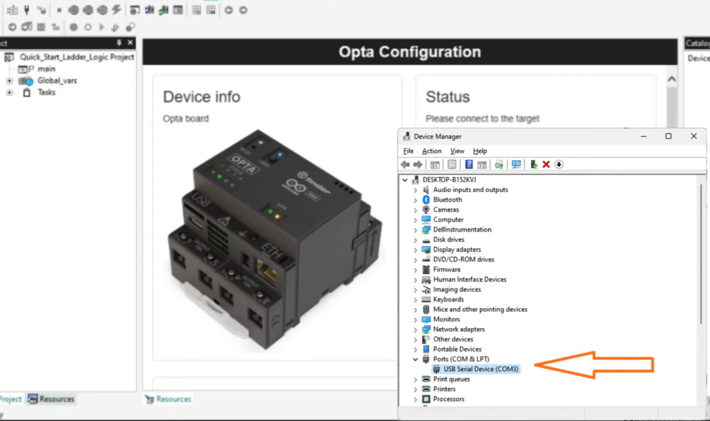
3. Select COM Port:
Go to “Tools” > “Port” and select the COM port that corresponds to your connected OPTA PLC. If you’re unsure which port to select, check your computer’s device manager or system information.
4. Download a Sample Sketch:
To ensure that your setup is working correctly, download a sample sketch (e.g., the “Blink” sketch) by going to “File” > “Examples” > “01.Basics” > “Blink”.
5. Modify LED Pin (if needed):
Depending on your OPTA PLC configuration, you may need to modify the LED pin in the Blink sketch. By default, it’s set to pin 13. Update it to the appropriate pin number if necessary.
6. Upload the Sketch:
Click the “Upload” button (right-arrow icon) in the Arduino IDE to compile and upload the sketch to your OPTA PLC.
You should see the LED on your OPTA PLC blink according to the sketch’s instructions, indicating a successful connection and upload.
Arduino OPTA IoT PLC – Quick Start Ladder Logic: Steps
1) Installing an Input Device
To get started with your ladder logic program, you’ll need an input device.
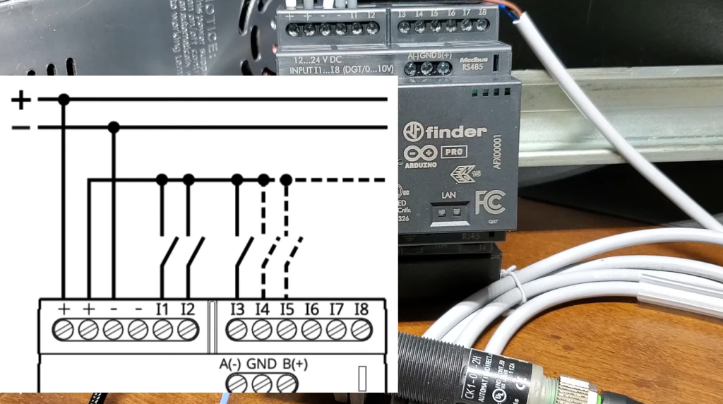
Prepare the Input Device:
Connect a push-button switch to one of the digital input pins on your OPTA IoT PLC. Make sure to connect one end to the digital input pin and the other end to the ground (GND) pin on the PLC [8].
Secure the Connections:
Ensure that the connections are secure and the switch is correctly wired.
2) Connection to the OPTA IoT PLC
Power On The PLC:
Ensure your OPTA IoT PLC is powered on.
Connect the PLC:
Use a USB-C cable to connect your computer to the OPTA IoT PLC.
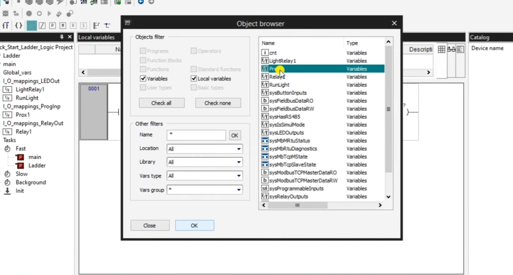
3) Configuring the Tags
Tags are essential for labeling and identifying inputs and outputs in ladder logic programming.
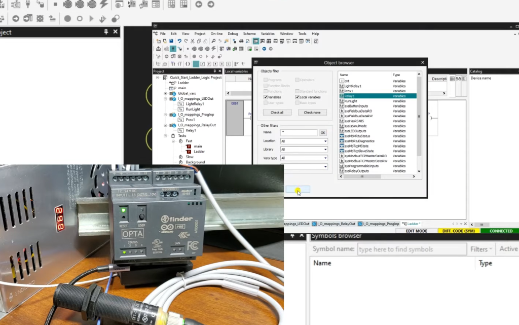
Launch the OPTA Software:
Open the OPTA software on your computer.
Create Tags:
In the OPTA software, create tags for your input device. For example, you can create a tag called “Push_Button” for the input connected to your push-button switch.
Assign Addresses:
Assign the appropriate addresses to your tags. These addresses correspond to the physical input and output points on your PLC.
4) Tasks and What They Do
Tasks in ladder logic programming define the logic that controls your automation system.
Create a Task:
In the OPTA software, create a new task and give it a meaningful name, such as “Button_Control”.
Add Ladder Logic Elements:
In your task, use ladder logic elements like “Examine If Closed (XIC)” and “Output Energize (OTE)” to create the desired logic. For example, you can set up a logic that activates an output when the push button is pressed.
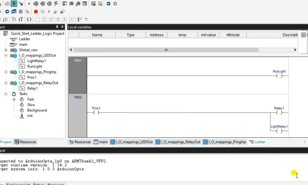
5) OPTA Basic Ladder Logic Program
Here’s an example of a basic ladder logic program for your push-button switch:
|—–[XIC]—-[ ]—–[OTE]——( )
| Push_Button | Output |
|—————–|—————–|
In this ladder logic, the “XIC” element checks if the push button is closed (pressed), and if it is, it energizes the “OTE” output, turning it on [9].
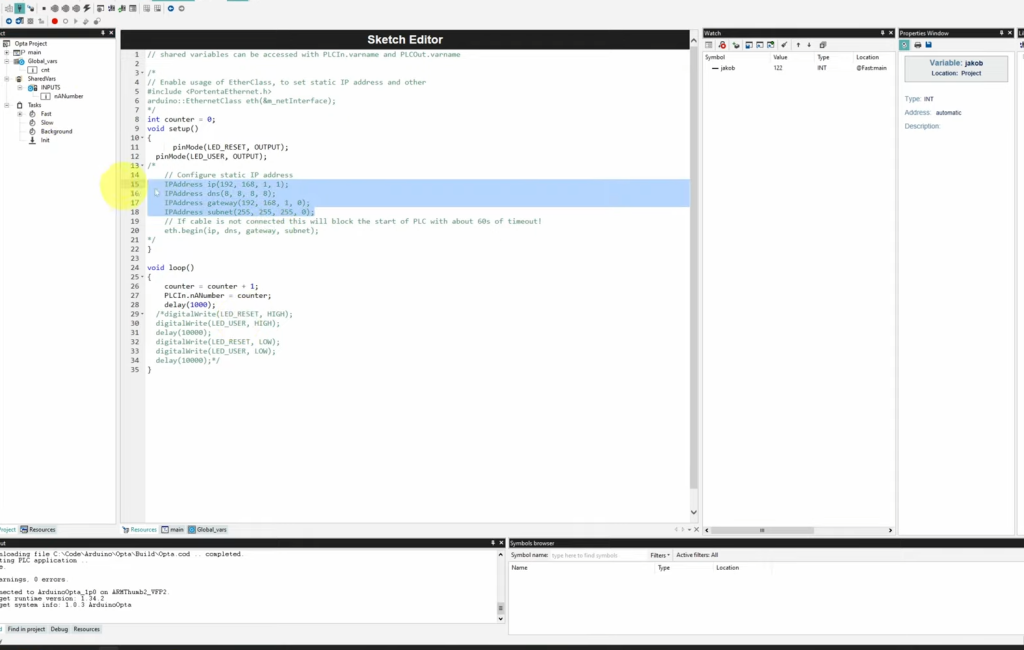
6) Programming Your Ladder Logic with OPTA
Now that you have created your ladder logic, it’s time to program it into your OPTA IoT PLC.
Compile Your Ladder Logic:
Compile your ladder logic program in the OPTA software to check for any errors or issues.
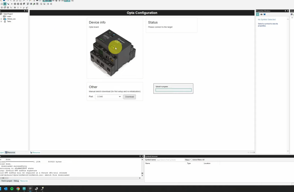
Download the Program:
Once your ladder logic program is error-free, download it to your OPTA IoT PLC using the OPTA software.
7) Download the Ladder Program to the OPTA Controller
Connect and Select PLC:
- Ensure your OPTA IoT PLC is connected to your computer via USB-C;
- In the OPTA software, select your PLC from the available options;
Download the Program:
Click the “Download” or “Program” button in the OPTA software to transfer your ladder logic program to the PLC.
8) Monitoring the Ladder Logic and Variables
After programming your ladder logic, you can monitor its operation and variables.
Monitor in Real-Time:
With your PLC powered on and connected, you can monitor the ladder logic program in real timereal time through the OPTA software. This allows you to observe the status of inputs, outputs, and ladder logic elements.
9) Troubleshooting:
If your ladder logic program isn’t behaving as expected, use the monitoring tools in the OPTA software to identify and address issues.
FAQ:
1. What is an Arduino OPTA?
The Arduino OPTA is a compact, versatile microcontroller board designed for industrial automation and control applications. It is part of the Arduino family and combines the ease of Arduino programming with robust features suitable for automation and control tasks. The OPTA boards often include features like digital and analog inputs, outputs, relay controls, communication interfaces, and compatibility with various industrial protocols.
2. What is OPTA PLC?
The term “OPTA PLC” refers to an Arduino OPTA microcontroller board used in Programmable Logic Controller (PLC) applications. A PLC is a digital computer designed for industrial control and automation, and the OPTA PLC variant is specifically tailored for such tasks. It allows users to create and execute ladder logic programs to control various processes and machinery in industrial settings.
3. How to use PLC software?
Using PLC software typically involves the following steps:
- Install PLC Programming Software: First, install the PLC programming software provided by the PLC manufacturer. Common software includes Siemens TIA Portal, Allen-Bradley RSLogix, or Schneider Electric EcoStruxure;
- Create a New Project: Start a new project in the software and define the hardware configuration, including the types and locations of inputs, outputs, and controllers;
- Write or Import PLC Program: Write your ladder logic or structured text program to define the control logic. You can also import existing programs or use pre-designed function blocks;
- Configure Communication: Set up communication parameters for connecting to the PLC hardware, such as choosing the communication port or Ethernet settings;
- Compile and Download: Compile your program to check for errors. Once it’s error-free, download the program to the PLC using a communication cable or network connection;
- Monitor and Debug: Use the software’s monitoring tools to observe the PLC’s behavior in real time. Debug any issues and make necessary adjustments to the program;
- Testing and Commissioning: After thorough testing and validation, commission the PLC system for regular operation;
4. Can you use a Raspberry Pi as a PLC?
Yes, you can use a Raspberry Pi as a PLC alternative for certain automation and control tasks. While Raspberry Pi boards are not traditional PLCs, they offer GPIO pins and the ability to run software like Python or C++ to control external devices.
However, Raspberry Pi lacks some of the industrial-grade features found in dedicated PLCs, so its use is often limited to less demanding applications.
5. Can I write C++ code in Arduino?
Yes, you can write C++ code when programming an Arduino. Arduino sketches are typically written in a subset of C++, and you can use standard C++ syntax and libraries in your Arduino projects. The Arduino IDE simplifies the programming process, but you can also write more complex C++ code if needed.
6. Can the Arduino be programmed in Python?
While Arduino is primarily programmed using the Arduino IDE with C/C++-based sketches, there are alternatives that allow you to program Arduino in Python. Projects like “Firmata” and “Arduino PySerial” enable communication between Python scripts and Arduino boards. This approach lets you control and interact with Arduino using Python code.
7. How to add code to Arduino?
To add code to an Arduino board, follow these steps:
- Install Arduino IDE: Download and install the Arduino IDE on your computer from the official Arduino website;
- Connect Arduino: Connect your Arduino board to your computer using a USB cable;
- Launch Arduino IDE: Open the Arduino IDE;
- Create or Open a Sketch: You can start a new sketch by going to “File” > “New” or open an existing one via “File” > “Open”;
- Write or Paste Code: In the Arduino IDE, write or paste your code into the sketch. Ensure it follows the correct syntax and structure for Arduino sketches;
- Verify and Compile: Click the checkmark icon (Verify) to check for syntax errors and compile your code;
- Upload to Arduino: Click the right-arrow icon (Upload) to compile and upload the code to your connected Arduino board
- Monitor Serial Output (Optional): If your sketch includes serial output, you can monitor it through the “Serial Monitor” in the Arduino IDE;
8. How much is the Arduino OPTA?
The price of an Arduino OPTA board can vary depending on the specific model, features, and supplier. Generally, Arduino boards are known for their affordability, with many entry-level models priced under $50. However, more advanced and feature-rich OPTA variants may cost more. Prices can also vary by region and availability.
9. How to use an Arduino compiler?
The Arduino IDE includes a built-in compiler that automatically compiles your Arduino sketches when you click the “Verify” or “Upload” button.
You don’t need to perform separate compilation steps. Here’s how to use it:
- Write Your Code: Write or paste your Arduino code into the Arduino IDE;
- Verify: Click the checkmark icon (Verify) to check your code for syntax errors. If there are errors, the IDE will display them in the message window at the bottom;
- Compile and Upload: Click the right-arrow icon (Upload) to compile and upload your code to the connected Arduino board. If there are no errors, the code will be compiled successfully and uploaded to the board;
The Arduino IDE handles the compilation process transparently, making it easy for users to write and test code on Arduino boards.
10. Can I program an Arduino without an Arduino IDE?
Yes, you can program an Arduino without the Arduino IDE. While the Arduino IDE provides a user-friendly environment for writing and uploading code, you have alternatives:
- PlatformIO: PlatformIO is an open-source ecosystem for IoT development that supports multiple development platforms, including Arduino. You can use PlatformIO with popular code editors like Visual Studio Code (VSCode) to write, compile, and upload Arduino code;
- AVR-GCC: For advanced users, you can use the AVR-GCC compiler directly with Makefiles to write and compile Arduino code. This method requires more manual setup and knowledge of the AVR-GCC toolchain;
These alternatives provide more flexibility and advanced features for programming Arduino boards but may have steeper learning curves compared to the Arduino IDE.
11. Is Arduino IDE free?
Yes, the Arduino IDE is free and open-source software (FOSS). You can download and use it without any cost. Arduino follows the principles of open-source hardware and software, making it accessible to a wide range of users and developers.
12. Can we replace PLC with Arduino?
In some cases, you can replace a traditional Programmable Logic Controller (PLC) with an Arduino for certain automation and control tasks. Arduino boards are versatile and cost-effective, making them suitable for smaller-scale automation projects and prototypes.
However, there are limitations to consider, such as the lack of industrial-grade reliability and compliance with specific industry standards. Large-scale or critical industrial applications often require dedicated PLCs designed for those purposes.
13. Does PLC require coding?
Yes, PLCs require coding, but the coding is done using ladder logic, structured text, or other specialized programming languages rather than traditional software programming languages like C++ or Python. Programmable Logic Controllers (PLCs) use ladder logic diagrams to create control programs for automation and control systems.
Programmers use graphical symbols and elements to define the logic and sequencing of operations in the system. So, while it’s not traditional coding, it involves creating logic programs to control industrial processes and machinery.
Useful Video: Programming the Arduino OPTA
References:
- https://accautomation.ca/arduino-opta-iot-plc-quick-start-ladder-logic/?expand_article=1
- https://www.reddit.com/r/PLC/comments/145ukb4/arduino_opta_good_or_garbage/
- https://www.dfrobot.com/product-2694.html
- https://emag.directindustry.com/2022/12/06/arduino-launches-opta-a-new-affordable-plc-solution-for-iiot-applications/
- https://www.electromaker.io/blog/article/embedded-world-2023-the-arduino-opta-an-all-in-one-solution-for-industrial-automation
- https://electronicslovers.com/2023/04/arduino-opta-plc-pros-cons.html
- https://docs.arduino.cc/tutorials/opta/getting-started
- https://www.solisplc.com/tutorials/arduino-opta
- https://control.com/technical-articles/ladder-logic-for-the-arduino-opta-plc-creating-your-first-program/