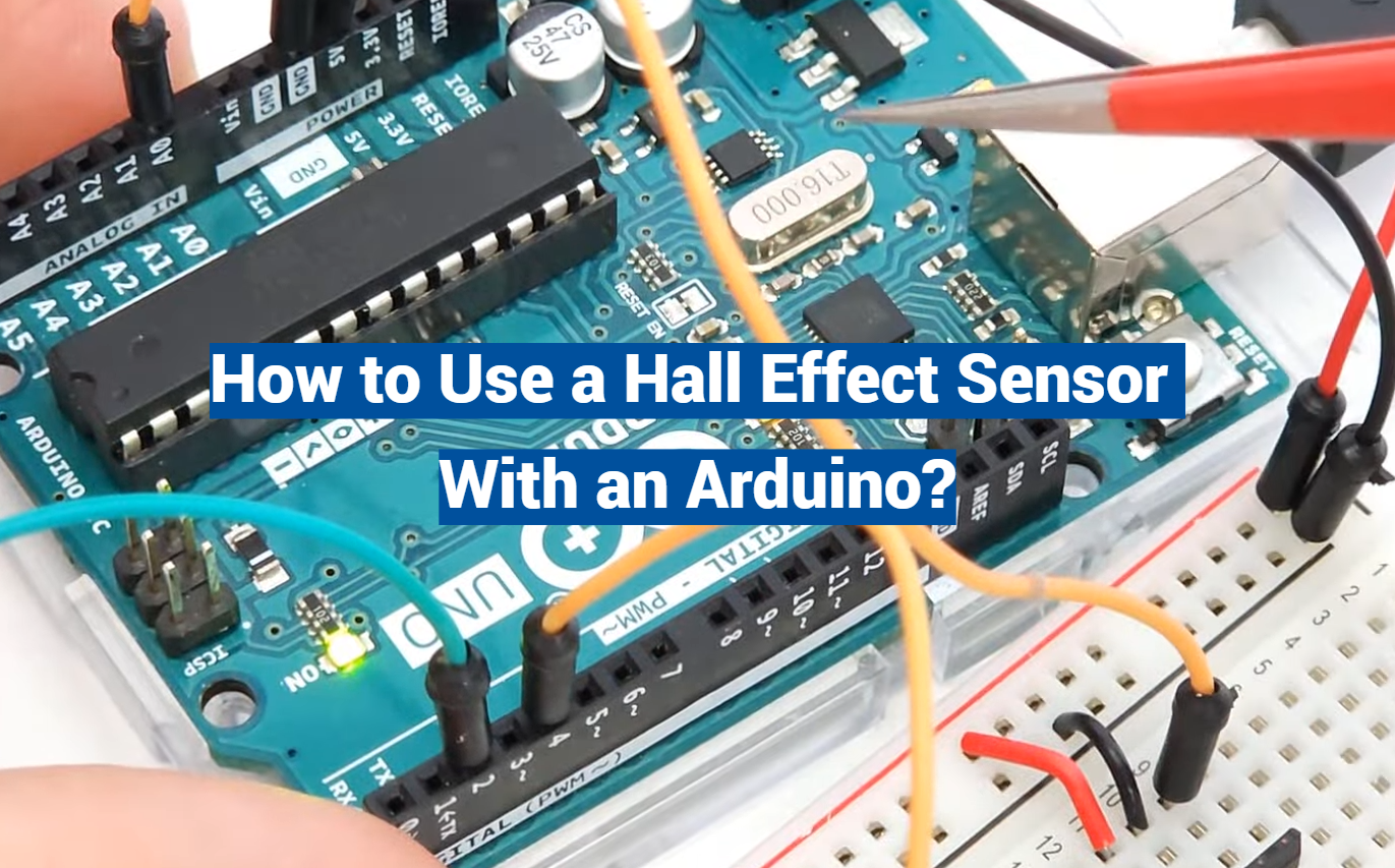
In this article, we will delve into the intriguing world of microcontrollers and sensors, specifically focusing on how to use a Hall Effect Sensor with an Arduino.
Understanding this relationship is fundamental for various applications, such as automobile ignition systems, tachometers, current sensors, brushless DC motor controllers, and speed control.
The Hall Effect sensor, which detects the presence of a magnetic field, can be connected to an Arduino in a few simple steps.
This guide will provide a comprehensive tutorial on using the Hall Effect sensor, including the necessary connections and programming instructions needed to bring your projects to life.
What Is a Hall Effect Sensor?
Here’s how a Hall effect sensor works:
- Basic Setup: A Hall effect sensor consists of a thin piece of semiconductor material, typically made of silicon. A voltage is applied across the sensor in a direction perpendicular to the flow of electric current;
- Magnetic Field Interaction: When a magnetic field is applied perpendicular to the semiconductor material, it exerts a force on the moving charge carriers (usually electrons) within the material. This force causes the charge carriers to be deflected to one side of the sensor, creating a voltage difference across the sensor;
- Output Voltage: The voltage difference generated across the Hall effect sensor is proportional to the strength of the magnetic field and the current flowing through the sensor. This voltage, known as the Hall voltage, can be measured and used to determine the characteristics of the magnetic field;
Hall effect sensors are used in a wide range of applications, including:
- Speed and Position Sensing: They can be used in automotive applications to measure the speed and position of rotating components such as the crankshaft and wheel speed sensors;
- Current Sensing: Hall effect sensors can measure the current flowing through a conductor without the need for direct electrical contact. This is commonly used in electronic circuits for current monitoring and protection;
- Proximity Detection: They are used to detect the presence or absence of nearby magnets or magnetic fields, making them suitable for proximity switches, door and window position sensors, and more;
- Brushless DC Motors: Hall effect sensors are often used in conjunction with brushless DC motors to provide feedback for rotor position, enabling precise motor control;
- Magnetic Field Measurement: They can be used as instruments to measure the strength and direction of magnetic fields, which is useful in scientific research and engineering applications;
- Security Systems: In security systems, Hall effect sensors can be used to detect the opening or closing of doors and windows;
Hall effect sensors are known for their durability, reliability, and accuracy in detecting magnetic fields, making them essential components in various electronic and industrial applications.
Overview Of Hall Effect Sensors:
Material
Hall Effect sensors are constructed using various materials, each with specific properties to suit different applications. The core material used in these sensors is semiconductor materials such as silicon, gallium arsenide, and indium arsenide [2].
These materials offer several advantages, including:
- High Sensitivity: Semiconductor materials exhibit a strong Hall Effect, making them highly sensitive to magnetic fields. This sensitivity is crucial for accurately measuring magnetic phenomena;
- Temperature Stability: Semiconductors have stable electrical characteristics over a wide temperature range, making them suitable for both high and low-temperature applications;
- Miniaturization: Semiconductor materials allow for the miniaturization of Hall Effect sensors, enabling their integration into compact electronic devices;
- Low Power Consumption: Hall Effect sensors made from semiconductor materials typically consume very little power, making them suitable for battery-powered applications;
- Cost-Effective: Mass production of semiconductor-based Hall Effect sensors has made them cost-effective and readily available;
Principle of Operation
The Hall Effect, on which these sensors rely, is a fundamental physical phenomenon that occurs when a magnetic field interacts with a current-carrying conductor.
The Hall Effect can be summarized as follows:
- Current Flow: When an electric current flows through a conductor (such as a semiconductor material), it consists of moving charged particles (electrons or holes);
- Magnetic Field: When a magnetic field is applied perpendicular to the direction of current flow, it exerts a force on the moving charged particles;
- Voltage Potential: As a result of this force, an electric potential difference (voltage) is generated perpendicular to both the current direction and the magnetic field direction. This voltage is known as the Hall voltage and is directly proportional to the magnetic field strength;
- Hall Effect Sensor Output: A Hall Effect sensor detects this Hall voltage and converts it into an electrical signal that can be measured and interpreted;
Scheme
Hall Effect sensors can be implemented in various configurations depending on the specific requirements of the application.
The most common schemes include:
- Linear Hall Effect Sensor: This type of sensor provides a linear output voltage proportional to the strength of the applied magnetic field. It is often used for position and proximity sensing, as well as in current measurement applications;
- Switch Hall Effect Sensor: Switch-type sensors have a digital output that changes state (from high to low or vice versa) when a predefined magnetic field threshold is reached. These sensors are used in applications such as door/window position sensing, rotational speed measurement, and presence detection;
- Wheel Speed Sensor: Hall Effect sensors can be incorporated into automotive wheel speed sensors to monitor wheel rotation. These sensors help with anti-lock braking systems (ABS) and traction control;
- Current Sensing: Hall Effect sensors are also employed for measuring current in electrical circuits. They are placed in series with the current-carrying conductor, and the magnetic field generated by the current is used to determine the current magnitude;
Code
Implementing Hall Effect sensors in electronic circuits often requires microcontrollers or digital signal processing devices to process sensor data [3].
Below is an example of Arduino code for interfacing a linear Hall Effect sensor with an Arduino board:
const int sensorPin = A0; // Analog pin to read sensor output
float voltage;
float magneticField;
void setup() {
Serial.begin(9600);
}
void loop() {
// Read the sensor voltage
int sensorValue = analogRead(sensorPin);
// Convert the analog value to voltage
voltage = (sensorValue / 1024.0) * 5.0;
// Calculate the magnetic field strength
magneticField = voltage / sensitivity; // Sensitivity is sensor-dependent
// Display the magnetic field strength
Serial.print(“Magnetic Field: “);
Serial.print(magneticField);
Serial.println(” Gauss”);
delay(1000); // Delay for 1 second
}
This code reads the analog output of the Hall Effect sensor, converts it to a voltage, and calculates the magnetic field strength. It then displays the magnetic field strength in Gauss on the Arduino’s serial monitor.
Result
The results obtained from Hall Effect sensors depend on their type and application.
Here are some common outcomes and findings when using Hall Effect sensors:
- Position and Proximity Sensing: Linear Hall Effect sensors provide a voltage output that linearly varies with the strength of the magnetic field. This voltage can be converted into position or distance measurements. For example, in automotive applications, wheel speed sensors use Hall Effect sensors to measure wheel rotation speed accurately;
- Switching Behavior: Switch-type Hall Effect sensors produce digital outputs that change state when a specific magnetic field threshold is reached. These sensors are often used to detect the opening and closing of doors or to monitor the presence of magnetic objects;
- Current Measurement: When employed for current sensing, Hall Effect sensors provide a direct measurement of the current passing through a conductor. This is particularly useful in applications like motor control, power monitoring, and battery management;
- Feedback Control: Hall Effect sensors are frequently used in feedback control systems, such as in motor control circuits, to ensure precise and stable operation. They provide real-time information about the magnetic field’s strength, allowing the system to make rapid adjustments as needed;
Applications
Hall Effect sensors find applications in various industries and fields due to their versatility and accuracy.
Some notable applications include:
- Automotive: Hall Effect sensors are integral components of automotive systems. They are used in wheel speed sensors, throttle position sensors, and crankshaft position sensors. These sensors contribute to critical functions like anti-lock braking systems (ABS), electronic stability control (ESC), and engine management;
- Industrial Automation: Hall Effect sensors are employed in industrial machinery for position and proximity sensing. They help control the movement of robotic arms, measure the position of conveyor belts, and monitor the presence of objects on assembly lines;
- Consumer Electronics: In consumer devices like smartphones and laptops, Hall Effect sensors are used to detect the opening and closing of flip covers, initiate screen rotations based on device orientation, and conserve power by turning off displays when not in use;
- Medical Devices: Hall Effect sensors play a role in medical equipment such as infusion pumps, where they monitor fluid flow rates and ensure precise medication delivery;
- Aerospace: In aerospace applications, Hall Effect sensors are utilized in sensors that monitor the position and orientation of aircraft components, contributing to flight stability and control;
- Energy and Power Management: Hall Effect current sensors are essential in energy and power management systems, helping to monitor and control electrical currents in power distribution networks;
- Security Systems: These sensors are used in security systems to detect the opening of doors and windows, triggering alarms when unauthorized access is detected [4];
Types of Hall Effect Sensors:
Unipolar Hall Effect Sensors
Unipolar Hall Effect sensors are named for their sensitivity to only one polarity of the magnetic field. They are also known as digital Hall Effect sensors because they produce digital output signals.
Features of Unipolar Hall Effect Sensors:
- Digital Output: Unipolar sensors generate a digital output signal that is either high (ON) or low (OFF) depending on the presence or absence of a magnetic field exceeding a specific threshold;
- Single-Polarity Sensitivity: These sensors are primarily sensitive to one polarity of the magnetic field. For example, they may detect the presence of a south pole but not a north pole, or vice versa;
- Simple Circuitry: Unipolar Hall Effect sensors require minimal external circuitry due to their digital nature. They are relatively easy to interface with microcontrollers or digital logic circuits;
- Low Power Consumption: They typically consume low power, making them suitable for battery-operated devices and applications requiring energy efficiency;
Applications of Unipolar Hall Effect Sensors:
- Proximity Detection: Unipolar sensors are commonly used in proximity detection applications, such as detecting the closing of doors, lids, or covers in appliances and security systems;
- Position Sensing: They find use in position sensing applications where the presence or absence of a magnetic marker or target indicates a specific position. For example, they are employed in rotary encoders;
- Speed Sensing: Unipolar Hall Effect sensors can be utilized in conjunction with a rotating target to measure the speed of a motor or a rotating object
- Magnetic Switches: These sensors are often used as magnetic switches to trigger actions or alarms when a magnetic field crosses a certain threshold;
Bipolar Hall Effect Sensors
Bipolar Hall Effect sensors, also known as analog Hall Effect sensors, have a different set of characteristics compared to their unipolar counterparts. They are sensitive to both polarities of magnetic fields and produce analog output signals.
Features of Bipolar Hall Effect Sensors:
- Analog Output: Bipolar sensors generate analog output voltage signals that vary continuously with changes in the magnetic field strength. The output voltage is proportional to the strength and polarity of the magnetic field;
- Dual-Polarity Sensitivity: These sensors can detect both north and south magnetic poles, providing bidirectional magnetic field sensing capabilities;
- Higher Resolution: Bipolar sensors offer higher resolution and sensitivity compared to unipolar sensors. They can measure a wider range of magnetic field strengths with precision;
- Versatile Voltage Levels: The analog output voltage can be customized to suit the specific application by using appropriate supply voltage and signal conditioning [5];
Applications of Bipolar Hall Effect Sensors:
- Current Sensing: Bipolar Hall Effect sensors are often used for current sensing in electronic circuits, allowing accurate measurement of current in both directions;
- Angle and Position Measurement: They are employed in rotary and linear position sensing applications where precise measurement of angles or distances is required. Examples include joystick controls and robotics;
- Magnetic Field Measurement: Bipolar sensors can be used in scientific instruments and geophysical equipment to measure and map magnetic fields in both directions;
- Motor Control: In motor control applications, bipolar Hall Effect sensors provide feedback on the position and speed of the motor rotor, enabling precise control of motor operations;
- Navigation and Compasses: Bipolar sensors are used in electronic compasses and navigation systems to determine the orientation and direction of vehicles and devices;
How Does a Hall Effect Sensor Work:
Here’s how a Hall Effect sensor works:
- Current Flow: In the core of a Hall Effect sensor, there is a thin strip or plate made of semiconductor material, typically silicon. When an electric current flows through this material, it consists of moving charged particles, usually electrons;
- Applied Magnetic Field: When an external magnetic field is introduced perpendicular to the direction of the current flow within the semiconductor material, it exerts a force on the moving charged particles (Lorentz force). The force causes the charged particles to deflect sideways;
- Hall Voltage Generation: Due to this deflection, an electric potential difference (voltage) is created across the semiconductor material, perpendicular to both the current direction and the magnetic field direction. This voltage is known as the Hall voltage;
- Measurement and Output: The Hall Effect sensor has electrodes positioned to detect this Hall voltage. It converts the Hall voltage into an electrical signal that can be measured and interpreted. Depending on the sensor type (unipolar or bipolar), this output can be either digital or analog;
- Magnetic Field Strength: The magnitude of the Hall voltage is directly proportional to the strength of the applied magnetic field. As the magnetic field strength increases, the Hall voltage also increases [6];
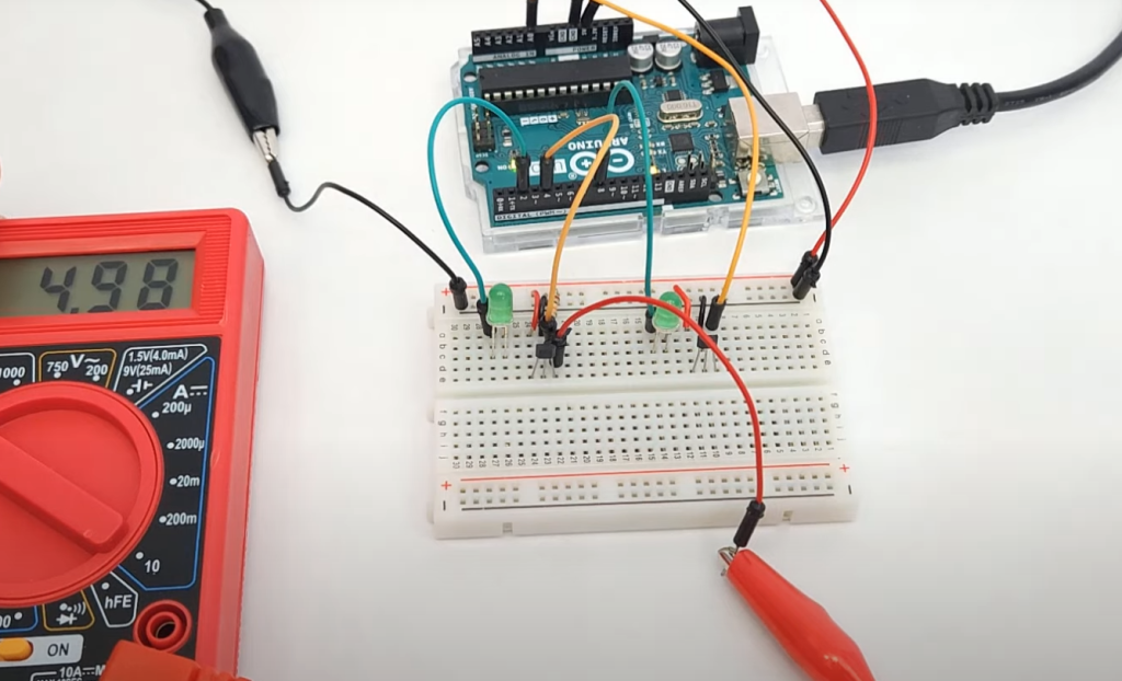
Making the Connections for the Arduino Hall Effect Sensor
To work with a Hall Effect sensor and an Arduino, you’ll need to make the following connections:
- Connect the power supply (typically 5V) to the VCC (power) pin of the Hall Effect sensor;
- Connect the ground (GND) of the power supply to the GND (ground) pin of the Hall Effect sensor;
- Connect the signal output pin of the Hall Effect sensor to one of the analog or digital input pins on the Arduino (e.g., A0 or D2);
- To ensure stability, it’s a good practice to connect a 10kΩ pull-up resistor between the signal output pin and the power supply voltage (VCC);
Uploading the Code and Testing the Arduino Hall Effect Sensor
Here’s a basic example of Arduino code to read the Hall Effect sensor’s output and print it to the serial monitor:
const int sensorPin = A0; // Replace with your actual sensor pin
int sensorValue;
void setup() {
Serial.begin(9600);
}
void loop() {
sensorValue = digitalRead(sensorPin); // Read the sensor value (0 or 1)
if (sensorValue == LOW) {
Serial.println(“Magnetic field detected!”);
} else {
Serial.println(“No magnetic field detected.”);
}
delay(1000); // Delay for 1 second before the next reading
}
Upload this code to your Arduino using the Arduino IDE.
Open the serial monitor (Tools > Serial Monitor) to view the sensor’s output.
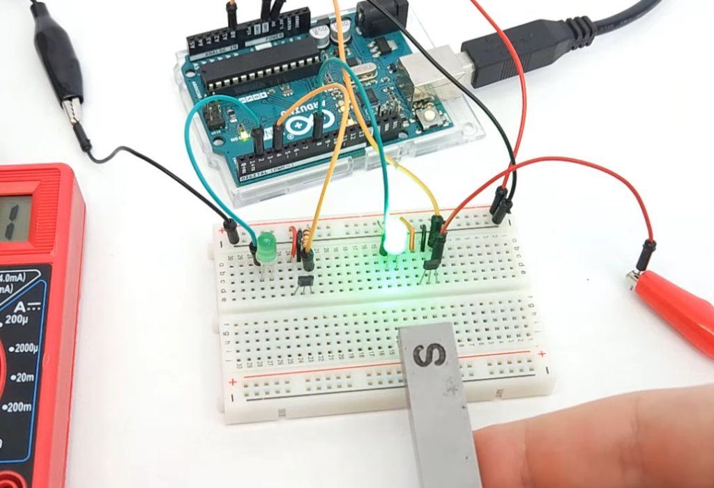
When a magnetic field is near the Hall Effect sensor, the serial monitor will display “Magnetic field detected!” Otherwise, it will show “No magnetic field detected”.
Hooking Up the Arduino Hall Effect Sensor to Your Project
Once you’ve successfully tested the Hall Effect sensor with your Arduino, you can integrate it into your project.
Here are some steps to consider:
- Mounting: Securely mount the Hall Effect sensor in a location where it can detect the magnetic field of interest. For example, if you’re using it for proximity sensing, position it near the object you want to detect;
- Power Supply: Ensure that the power supply voltage is stable and suitable for your sensor. Check the sensor’s datasheet for specific voltage requirements;
- Signal Processing: Depending on your project’s requirements, you may need to process the sensor’s output further. For example, you can use conditional statements in your Arduino code to trigger specific actions based on the sensor’s readings;
- Integration: Connect the sensor to other components or devices as needed. This may involve controlling relays, LEDs, or other actuators based on the Hall Effect sensor’s input [7];
Control a Relay with Arduino and Hall Effect Sensor
To control a relay with an Arduino and a Hall Effect sensor, follow these additional steps:
- Connect a Relay: Connect a relay module to the Arduino. Relay modules typically have input pins (IN, GND) and output pins (COM, NO, NC). Connect the Hall Effect sensor’s signal pin to the Arduino and configure the code to control the relay based on the sensor’s readings;
- Code Modification: Modify your Arduino code to include relay control based on the Hall Effect sensor’s output;
Here’s a basic example:
const int sensorPin = A0; // Replace with your actual sensor pin
const int relayPin = 7; // Replace with your relay control pin
int sensorValue;
void setup() {
pinMode(relayPin, OUTPUT);
Serial.begin(9600);
}
void loop() {
sensorValue = digitalRead(sensorPin);
if (sensorValue == LOW) {
Serial.println(“Magnetic field detected!”);
digitalWrite(relayPin, HIGH); // Turn on the relay
} else {
Serial.println(“No magnetic field detected.”);
digitalWrite(relayPin, LOW); // Turn off the relay
}
delay(1000);
}
- Relay Load: Connect the load (e.g., a lamp or another device) to the relay’s output pins (COM and NO). When the Hall Effect sensor detects a magnetic field, it will turn on the relay, thereby activating the connected load;
- Testing: Upload the modified code to your Arduino and test the setup with the relay and Hall Effect sensor. When a magnetic field is detected, the relay should switch on the connected load, and when no magnetic field is present, the relay should turn it off;
This setup can be used for various applications, such as turning on lights when a magnetic door sensor is triggered or controlling machinery based on the presence of a magnetic object. Ensure that all electrical connections are secure and follow safety precautions when working with high-voltage devices.
How to Use a Hall Effect Sensor With an Arduino:
Interfacing Hall Effect Sensor with Arduino
What You’ll Need:
- Arduino board (e.g., Arduino Uno);
- Hall Effect sensor module;
- LED;
- 220-ohm resistor;
- Breadboard and jumper wires;
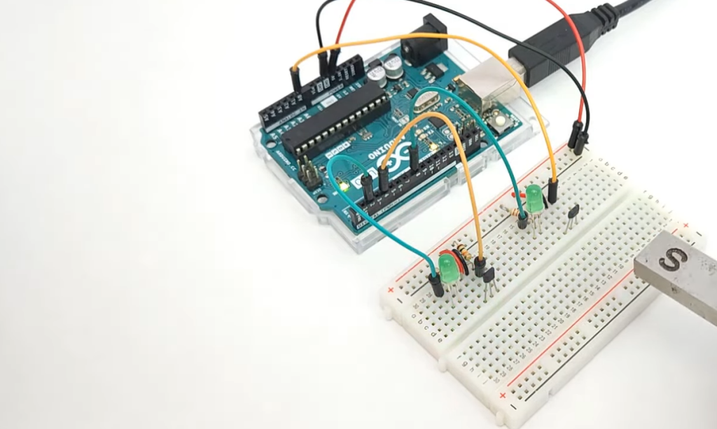
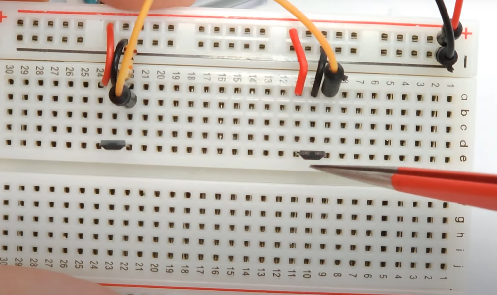
Connect the Hall Effect Sensor to Pin 10
Locate the Hall Effect sensor module. It typically has three pins: VCC, GND, and OUT.
Connect the OUT pin of the Hall Effect sensor module to digital pin 10 on the Arduino. This pin will be used to read the sensor’s output.
Connect the Hall Effect Sensor to 5V
Connect the VCC pin of the Hall Effect sensor module to the 5V output on the Arduino. This provides power to the sensor.
Connect the Hall Effect Sensor to the Ground
Connect the GND pin of the Hall Effect sensor module to one of the GND (ground) pins on the Arduino to complete the electrical connections. Now that the Hall Effect sensor is properly interfaced with the Arduino, let’s proceed to create a simple project [8].
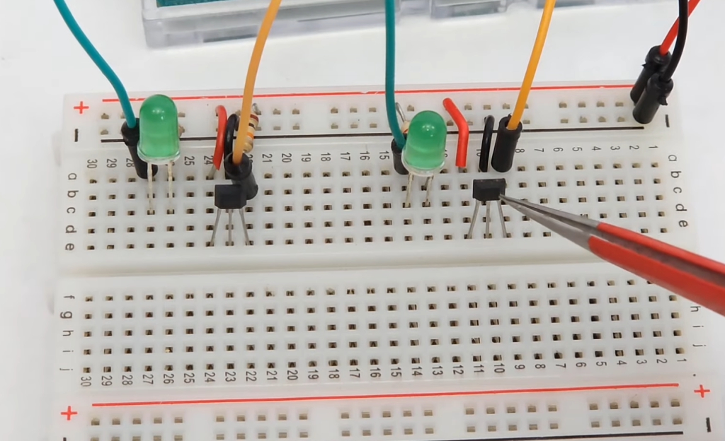
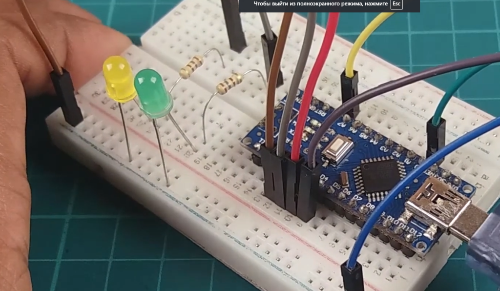
Insert LED Into Breadboard
Place the LED into the breadboard. LEDs have two leads: a longer positive lead (anode) and a shorter negative lead (cathode).
Connect the positive lead (anode) of the LED to any available row on the breadboard.
Insert 220 Ohm Resistor into the Breadboard
Insert the 220-ohm resistor into the breadboard, connecting one end to the same row as the positive lead of the LED.
Connect the other end of the 220-ohm resistor to digital pin 13 on the Arduino. This pin will be used to control the LED.
Connect LED to Ground
Connect the shorter negative lead (cathode) of the LED to a different row on the breadboard.
Connect a jumper wire from the same row where the LED’s cathode is connected to one of the GND (ground) pins on the Arduino. This completes the circuit for the LED.
With the hardware connections in place, it’s time to upload the code to your Arduino.
Upload the Code
Here’s a simple Arduino code that reads the Hall Effect sensor’s output and turns the LED on or off based on the presence of a magnetic field:
const int hallEffectPin = 10; // Pin connected to the Hall Effect sensor
const int ledPin = 13; // Pin connected to the LED
int sensorValue; // Variable to store the sensor value
void setup() {
pinMode(ledPin, OUTPUT); // Set the LED pin as an output
pinMode(hallEffectPin, INPUT);// Set the Hall Effect sensor pin as an input
Serial.begin(9600); // Initialize serial communication for debugging
}
void loop() {
sensorValue = digitalRead(hallEffectPin); // Read the sensor value
if (sensorValue == LOW) {
// Magnetic field detected
digitalWrite(ledPin, HIGH); // Turn on the LED
Serial.println(“Magnetic field detected!”);
} else {
// No magnetic field detected
digitalWrite(ledPin, LOW); // Turn off the LED
Serial.println(“No magnetic field detected.”);
}
delay(1000); // Delay for 1 second before the next reading
}
- Copy the code above and paste it into the Arduino IDE.
- Select your Arduino board and COM port from the “Tools” menu.
- Click the “Upload” button to upload the code to your Arduino board.
- Open the Arduino Serial Monitor (Tools > Serial Monitor) to view the sensor’s output.
Now, when you bring a magnet close to the Hall Effect sensor, the LED connected to pin 13 should turn on, and the Serial Monitor will display “Magnetic field detected!” When the magnet is removed, the LED should turn off, and it will display “No magnetic field detected” [9].
FAQ:
1. What is the input voltage for the hall effect sensor?
The input voltage for a Hall Effect sensor typically depends on the specific model and manufacturer, but many Hall Effect sensors operate at a supply voltage of 3.3V or 5V. You should check the datasheet for your particular sensor to determine its recommended voltage range.
2. How to test the hall effect sensor module?
To test a Hall Effect sensor module, follow these steps:
- Connect the sensor module to an appropriate power source and ground;
- Use a magnet or a magnetic source (e.g., a magnetic field) to approach the sensor;
- Observe the sensor’s output. If it’s a digital sensor, it will change its state (high to low or vice versa) when a magnetic field is detected. For analog sensors, the output voltage will vary based on the strength of the magnetic field;
You can also use an Arduino or a multimeter to read and display the sensor’s output for more detailed testing and analysis.
3. What is the range of hall effect sensors?
The range of Hall Effect sensors can vary significantly based on the sensor’s specifications and intended application. Some Hall Effect sensors are designed for low-field applications with small ranges, while others can detect magnetic fields over larger distances, up to several centimeters or more. It’s essential to refer to the datasheet for the specific sensor you are using to determine its range.
4. What do the hall effect sensors sense?
Hall Effect sensors primarily sense the presence and strength of magnetic fields. They can detect the presence of magnets, ferrous objects, or any magnetic material that affects the magnetic field in their proximity.
5. How do you use hall effect sensors?
To use Hall Effect sensors, you typically follow these steps:
- Connect the sensor to an appropriate power supply and ground;
- Position the sensor in the desired location to detect the magnetic field of interest;
- Read the sensor’s output using an Arduino, microcontroller, or other measurement devices;
- Interpret the sensor’s output to trigger specific actions or obtain data related to the magnetic field;
6. How to connect an Arduino to a hall effect sensor?
To connect an Arduino to a Hall Effect sensor, you need to make electrical connections as described in your project. Typically, you’ll connect the sensor’s power (VCC) to 5V, the ground (GND) to GND, and the output pin (OUT) to one of the digital or analog pins on the Arduino. Refer to the specific wiring instructions and code examples in your project or datasheet.
7. How do you activate a hall effect sensor?
Hall Effect sensors are passive devices; they don’t require activation like some other sensors. They are always ready to detect magnetic fields as long as they are powered and properly connected.
8. Does a hall effect sensor need a resistor?
The need for a resistor in a Hall Effect sensor circuit depends on the specific sensor module and application. Some Hall Effect sensors come with built-in pull-up or pull-down resistors. In cases where additional resistors are required, it’s typically to ensure proper voltage levels and signal conditioning, especially when connecting to a microcontroller’s digital input.
9. Are hall effect sensors digital or analog?
Hall Effect sensors can be both digital and analog, depending on their design and output. Digital Hall Effect sensors provide discrete output states (high or low) to indicate the presence of a magnetic field. Analog Hall Effect sensors produce a continuous output voltage that varies with the strength of the magnetic field.
10. What output does a hall effect sensor give?
The output of a Hall Effect sensor can be either digital or analog. Digital sensors provide a binary output, usually in the form of a high or low signal to indicate the presence or absence of a magnetic field. Analog sensors produce a voltage output that varies proportionally with the strength of the magnetic field.
11. Do hall effect sensors produce a digital signal?
Some Hall Effect sensors produce a digital signal, providing a high or low output based on the presence or absence of a magnetic field. These are often referred to as digital Hall Effect sensors. Other Hall Effect sensors provide analog output signals that change in voltage based on the strength of the magnetic field.
12. What devices use hall effect sensors?
Hall Effect sensors are used in a wide range of devices and applications, including automotive systems (wheel speed sensors, position sensors), industrial machinery (proximity sensors, current sensors), consumer electronics (smartphones, laptops), medical devices, security systems, and more.
13. Is a hall effect sensor a speed sensor?
Yes, Hall Effect sensors are commonly used as speed sensors in various applications. For example, they can be used to measure the speed of rotating objects, such as the wheels in an automotive system or the rotor in a motor. By detecting the rate of change in the magnetic field, they provide feedback on rotational speed.
14. What are the disadvantages of hall effect sensors?
While Hall Effect sensors have many advantages, they also have some limitations:
- Susceptibility to temperature variations: Hall Effect sensors may exhibit drift in their output with changing temperatures;
- Limited range: Some Hall Effect sensors have limited detection ranges, which may not be suitable for all applications;
- Magnetic interference: Strong external magnetic fields can affect the accuracy of measurements;
- Power consumption: Although generally low, power consumption may be a consideration in battery-powered applications;
It’s important to select the right sensor for your specific application to minimize these disadvantages.
15. Can a hall effect sensor detect metal?
Hall Effect sensors are primarily designed to detect magnetic fields, not metal directly. However, they can indirectly detect metal objects if those objects have magnetic properties or if magnets are attached to them. For direct metal detection, other sensors like proximity sensors or inductive sensors are typically more suitable.
Useful Video: How to Use a Hall Effect Sensor with Arduino (Lesson #31)
References:
- https://littlebirdelectronics.com.au/guides/67/hall-effect-sensor-with-arduino
- https://maker.pro/arduino/tutorial/how-to-use-a-hall-effect-sensor-with-arduino
- https://www.aranacorp.com/en/using-a-hall-effect-sensor-with-arduino/
- https://www.electronics-lab.com/project/using-hall-effect-sensor-arduino/
- https://circuitdigest.com/microcontroller-projects/interfacing-hall-effect-sensor-module-with-arduino
- https://microcontrollerslab.com/hall-effect-sensor-module-arduino-circuit-code/
- https://www.electronicshub.org/hall-effect-sensor-with-arduino/
- https://www.instructables.com/Arduino-Hall-Effect-Sensor-With-Interrupts/
- https://techatronic.com/hall-effect-sensor-with-arduino-hall-effect-sensor/