In the vast world of electronics, photoresistors play a pivotal role due to their light-sensitive properties. This article will guide you step-by-step through the process of interfacing a photoresistor with an Arduino microcontroller. You’ll learn how the resistance of these components changes with light intensity and how to harness this property to control various electronic devices.
Whether you aim to automate your home lighting system, design a light-tracking device, or create a light-activated alarm, understanding the interaction between photoresistors and Arduinos is key. Dive in to explore the fascinating possibilities of this light-dependent resistor.
What Is A Photoresistor?
Photoresistors are used in many devices to detect light, such as light-sensitive timing devices, light-activated alarms, street lighting systems, and in-camera light meters. They are also used in some types of high-gain audio amplifiers, synthesizers, and various types of light sensors because they are inexpensive, long-lasting, and have fast response times.
It’s important to note that a photoresistor is a passive component meaning it does not produce light or energy but rather reacts to it. So, when light falls upon it, the resistance changes. This change in resistance can then be measured and an appropriate signal is sent to other electronics for further processing.
How Does A Photoresistor Work?
At its core, a photoresistor is a type of resistor whose electrical resistance changes in response to the amount of light it receives. This remarkable characteristic is the foundation of its operation and makes it a vital component in various light-sensing applications.
Basic Structure
A photoresistor typically consists of a semiconductor material, often cadmium sulfide (CdS) or cadmium selenide (CdSe), sandwiched between two electrical terminals. The semiconductor material used in a photoresistor is known as the intrinsic layer. Unlike standard resistors that have a fixed resistance value, the resistance of a photoresistor varies with the intensity of incident light.
The Photoelectric Effect
To understand how a photoresistor works, it’s essential to grasp the concept of the photoelectric effect. This phenomenon, first described by Albert Einstein in 1905, involves the emission of electrons from a material when it is exposed to light [2].
In the case of photoresistors, when photons (particles of light) strike the semiconductor material, they excite the electrons within it, giving them enough energy to break free from their atomic bonds and move through the material.
These liberated electrons create an electrical current when they flow from the illuminated semiconductor material to one of the electrical terminals.
Resistance and Illuminance
The key feature of a photoresistor is its ability to change its resistance depending on the amount of light it receives. This change in resistance is not linear but exhibits an inverse relationship with the illuminance, which is a measure of the intensity of incident light.
When exposed to more light, a photoresistor’s resistance decreases, allowing more current to flow through it. Conversely, in low light conditions, the resistance of the photoresistor increases, reducing the current flow.
Applications of Photoresistors
The unique characteristics of photoresistors make them indispensable in a wide range of applications, both simple and complex.
Here are a few notable uses:
- Light Sensing: Photoresistors are commonly employed in automatic lighting systems, such as streetlights that turn on when it gets dark and off when it’s light;
- Camera Exposure Control: In photography, photoresistors are used to control the exposure settings of cameras. They can automatically adjust the aperture and shutter speed based on the available light.
- Security Systems: Photoresistors can be integrated into security systems to detect unauthorized intrusions by sensing changes in ambient light;
- Solar Panels: They are used in solar panels to optimize the orientation of the panels for maximum energy generation by tracking the position of the sun;
- Smoke Detectors: Photoresistors are used in smoke detectors to sense the scattering of light caused by smoke particles, triggering an alarm;
- Automotive Lighting: In automobiles, photoresistors are used for automatic headlight control, ensuring that headlights are turned on when it’s dark;
Photoresistor Sensor Features
When choosing a photoresistor for a specific application, it’s crucial to consider its features and specifications.
Here are some of the key characteristics that differentiate photoresistor sensors:
- Resistance Range: Photoresistors come in various resistance ranges, from a few hundred ohms to several megaohms. The choice of resistance range depends on the specific application and the desired sensitivity to light changes;
- Response Time: The response time of a photoresistor refers to how quickly it can react to changes in light intensity. Faster response times are essential for applications where rapid adjustments are required, such as camera exposure control;
- Spectral Response: Photoresistors have different spectral responses, meaning they may be more sensitive to certain wavelengths of light. Some are optimized for visible light, while others may be sensitive to infrared or ultraviolet light;
- Dark Resistance: Dark resistance is the resistance of a photoresistor when it is in complete darkness. It is a crucial parameter for determining the sensor’s baseline resistance and its ability to function in low light conditions;
- Power Rating: The power rating of a photoresistor indicates the maximum amount of power it can handle without getting damaged. Choosing a photoresistor with an appropriate power rating is vital to ensure the sensor’s longevity and reliability;
- Operating Temperature Range: Photoresistors have specific temperature ranges within which they operate optimally. It’s important to choose a sensor that can withstand the temperature conditions of the intended application [3];
How to Use Photoresistors to Detect Light on an Arduino:
Photoresistors, also known as light-dependent resistors (LDRs), are fantastic components for creating light-sensing projects with Arduino. They can be used to build applications such as automatic lighting systems, sun trackers, and more.
Setup a Photoresistor On the Arduino
Components You’ll Need:
- Arduino board (e.g., Arduino Uno);
- Photoresistor (LDR);
- Resistor (10kΩ);
- Breadboard and jumper wires;
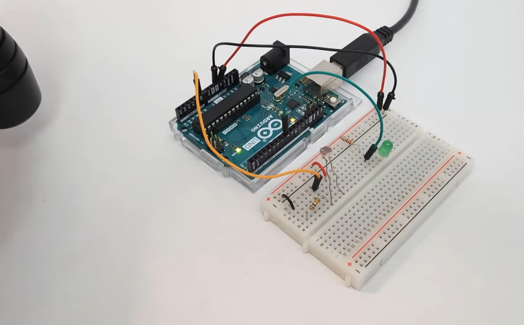
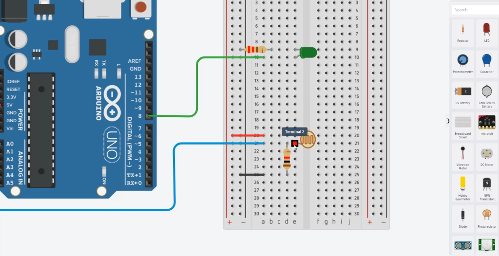
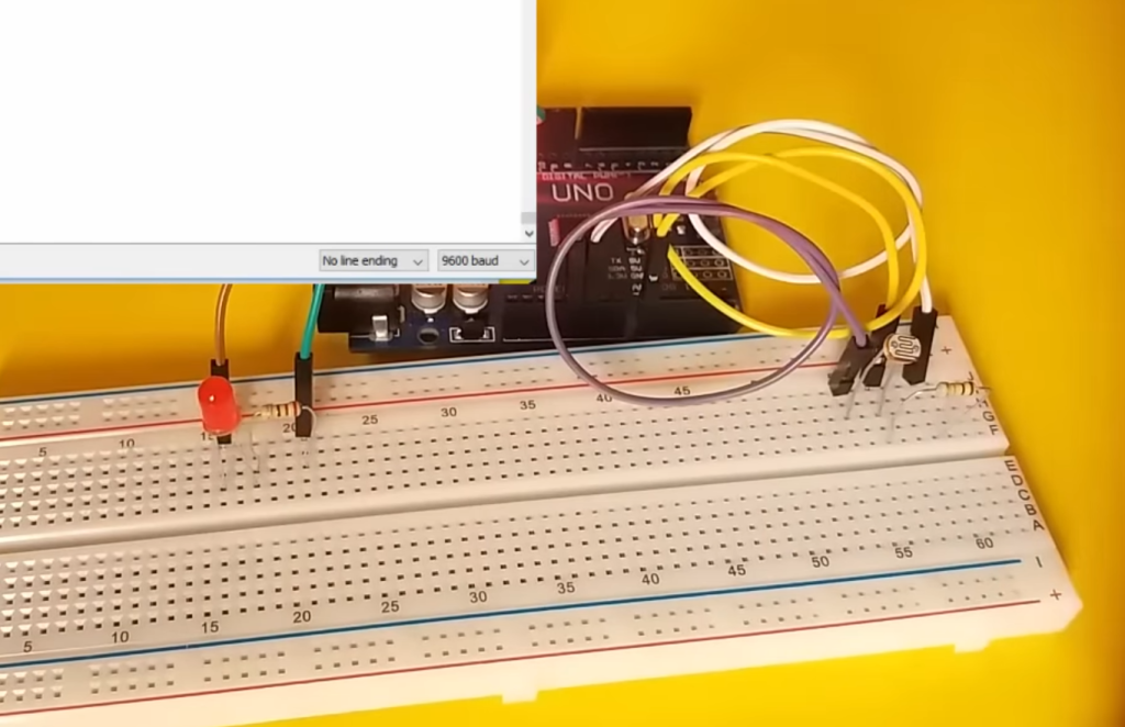
Step 1: Wiring:
- Place the photoresistor on the breadboard;
- Connect one end of the photoresistor to the 5V pin on the Arduino;
- Connect the other end of the photoresistor to one leg of the 10kΩ resistor;
- Connect the other leg of the 10kΩ resistor to the GND (ground) pin on the Arduino;
- Connect a jumper wire from the point where the photoresistor and resistor meet to an analog input pin on the Arduino (e.g., A0);
Your setup should resemble the following diagram:
Arduino 5V ———- Photoresistor ———- 10kΩ Resistor ———- GND
|
Analog Pin (e.g., A0)
Program a Photoresistor On the Arduino
Step 1: Arduino Code
Now, let’s write a simple Arduino sketch to read the light level detected by the photoresistor and display it on the Serial Monitor. This code will help you understand the values your photoresistor generates in different lighting conditions.
void setup() {
// Initialize serial communication
Serial.begin(9600);
}
void loop() {
// Read the value from the photoresistor
int photoresistorValue = analogRead(A0);
// Print the value to the Serial Monitor
Serial.print(“Light Level: “);
Serial.println(photoresistorValue);
// Add a short delay
delay(1000); // Read and display values every second
}
Step 2: Uploading the Code:
- Open the Arduino IDE on your computer;
- Connect your Arduino board to the computer using a USB cable;
- Select the correct board and port from the “Tools” menu in the Arduino IDE;
- Copy the code above and paste it into the Arduino IDE;
- Click the “Upload” button to upload the code to your Arduino board [4];
Programming a Photoresistor to Control Things
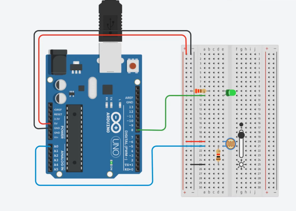
Step 1: Wiring the LED:
- Place an LED on the breadboard;
- Connect the longer (anode) leg of the LED to a current-limiting resistor (e.g., 220Ω);
- Connect the other end of the resistor to a digital pin on the Arduino (e.g., pin 13);
- Connect the shorter (cathode) leg of the LED to the GND (ground) pin on the Arduino;
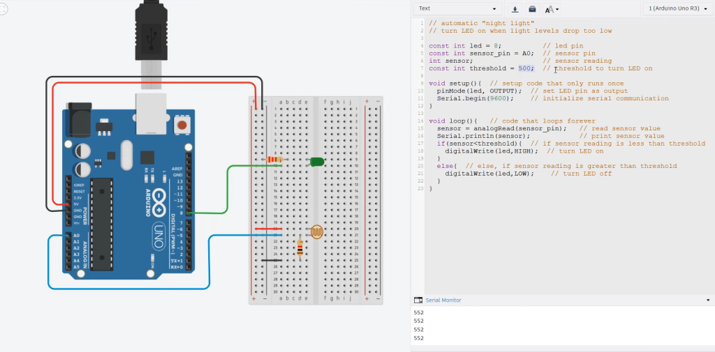
Step 2: Arduino Code for Controlling the LED
Modify the Arduino code to control the LED based on the light level. In this example, we’ll turn the LED on when the light level is below a certain threshold.
const int photoresistorPin = A0; // Analog pin for the photoresistor
const int ledPin = 13; // Digital pin for the LED
const int threshold = 500; // Set your desired threshold value
void setup() {
// Initialize serial communication
Serial.begin(9600);
// Set the LED pin as an output
pinMode(ledPin, OUTPUT);
}
void loop() {
// Read the value from the photoresistor
int photoresistorValue = analogRead(photoresistorPin);
// Print the value to the Serial Monitor
Serial.print(“Light Level: “);
Serial.println(photoresistorValue);
// Control the LED based on the light level
if (photoresistorValue < threshold) {
digitalWrite(ledPin, HIGH); // Turn on the LED
} else {
digitalWrite(ledPin, LOW); // Turn off the LED
}
// Add a short delay
delay(1000); // Read and control the LED every second
}
Step 3: Uploading the Modified Code
- Make sure your Arduino board is still connected to your computer;
- Modify the code as shown above;
- Click the “Upload” button in the Arduino IDE to upload the modified code to your Arduino board [5];
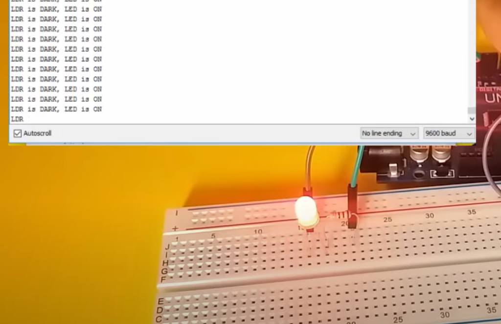
Now, your Arduino will control the LED based on the light level detected by the photoresistor. When the light level falls below the threshold, the LED will turn on, and when it’s above the threshold, the LED will turn off. This simple project demonstrates the power of photoresistors in creating light-controlled applications with Arduino. You can further expand upon this foundation to build more sophisticated projects that respond to changes in light conditions.
Interfacing Photoresistor (LDR) Sensor with Arduino:
Required Materials
1) Hardware Components:
- Arduino Board: You can use any Arduino board, such as Arduino Uno, Arduino Nano, or Arduino Mega, depending on your project requirements;
- Photoresistor (LDR): The heart of the light-sensing system, the photoresistor, is the primary sensor that changes resistance based on the intensity of light;
- Resistor (10kΩ): You’ll need a resistor to create a voltage divider circuit with the photoresistor. A 10kΩ resistor is commonly used;
- Breadboard: A breadboard is used to build a prototype and easily connect components;
- Jumper Wires: You’ll need jumper wires to connect the components on the breadboard and interface them with the Arduino;
2) Software Apps
Arduino IDE: Download and install the Arduino Integrated Development Environment (IDE) on your computer. You’ll use this software to write, upload, and manage the Arduino code.
Step 1: Wiring:
- Place the photoresistor on the breadboard;
- Connect one leg of the photoresistor to the 5V pin on the Arduino;
- Connect the other leg of the photoresistor to one end of the 10kΩ resistor;
- Connect the other end of the 10kΩ resistor to the GND (ground) pin on the Arduino;
- Connect a jumper wire from the junction between the photoresistor and the resistor to an analog input pin on the Arduino (e.g., A0);
Here’s a simplified diagram of the wiring:
Arduino 5V ———- Photoresistor ———- 10kΩ Resistor ———- GND
|
Analog Pin (e.g., A0)
Step 2: Arduino Code
Now, let’s write a simple Arduino sketch to read the light level detected by the photoresistor and display it on the Serial Monitor.
void setup() {
// Initialize serial communication
Serial.begin(9600);
}
void loop() {
// Read the value from the photoresistor
int photoresistorValue = analogRead(A0);
// Print the value to the Serial Monitor
Serial.print(“Light Level: “);
Serial.println(photoresistorValue);
// Add a short delay
delay(1000); // Read and display values every second
}
Step 3: Uploading the Code:
- Open the Arduino IDE on your computer;
- Connect your Arduino board to the computer using a USB cable;
- Select the correct board and port from the “Tools” menu in the Arduino IDE;
- Copy the code provided above and paste it into the Arduino IDE;
- Click the “Upload” button in the Arduino IDE to upload the code to your Arduino board [6];
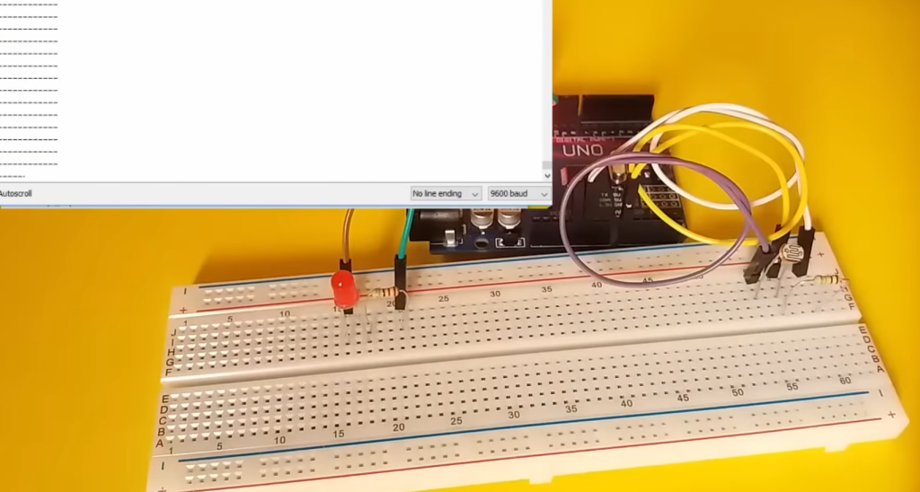
Step 4: Testing the Setup
Once the code is successfully uploaded, open the Serial Monitor in the Arduino IDE by clicking “Tools” > “Serial Monitor” or pressing Ctrl + Shift + M (or Cmd + Shift + M on Mac).
Interfacing LDR Sensor with Arduino:
1) Components Required:
- Arduino board (e.g., Arduino Uno);
- LDR (Light-Dependent Resistor);
- Resistor (10kΩ);
- Breadboard;
- Jumper wires;
2) Circuit Diagram:
- Connect one end of the LDR to the 5V pin on the Arduino;
- Connect the other end of the LDR to one leg of the 10kΩ resistor;
- Connect the other leg of the 10kΩ resistor to the GND (ground) pin on the Arduino;
- Connect a jumper wire from the junction between the LDR and the resistor to an analog input pin on the Arduino (e.g., A0);
The following simplified diagram illustrates the connections:
Arduino 5V ———- LDR ———- 10kΩ Resistor ———- GND
|
Analog Pin (e.g., A0)
3) Arduino Code for Reading LDR Sensor Values
Now, let’s write a simple Arduino sketch to read the light level detected by the LDR sensor and display it on the Serial Monitor.
void setup() {
// Initialize serial communication
Serial.begin(9600);
}
void loop() {
// Read the value from the LDR sensor
int ldrValue = analogRead(A0);
// Print the value to the Serial Monitor
Serial.print(“LDR Value: “);
Serial.println(ldrValue);
// Add a short delay
delay(1000); // Read and display values every second
}
4) Uploading and Testing the Code:
- Open the Arduino IDE on your computer;
- Connect your Arduino board to the computer using a USB cable;
- Select the correct board and port from the “Tools” menu in the Arduino IDE;
- Copy the code provided above and paste it into the Arduino IDE;
- Click the “Upload” button in the Arduino IDE to upload the code to your Arduino board;
- Open the Serial Monitor in the Arduino IDE by clicking “Tools” > “Serial Monitor” or pressing Ctrl + Shift + M (or Cmd + Shift + M on Mac);
You should see the LDR sensor values displayed in the Serial Monitor. These values will change as you expose the LDR to different light levels.
FAQ:
1. How to control the LED using a photoresistor (LDR) with Arduino?
To control an LED using a photoresistor (LDR) with Arduino, you can follow these steps:
- Connect the LDR in series with a resistor (e.g., 10kΩ) to create a voltage divider circuit;
- Connect one end of the LDR to the 5V pin on the Arduino;
- Connect the other end of the LDR to one leg of the resistor;
- Connect the other leg of the resistor to the GND (ground) pin on the Arduino;
- Connect a jumper wire from the junction between the LDR and the resistor to an analog input pin on the Arduino (e.g., A0);
- Read the analog value from the LDR using analogRead() in the Arduino code;
Use conditional statements to control the LED based on the LDR’s readings. For example, if the LDR value is below a certain threshold, turn the LED on; otherwise, turn it off.
2. How to create a hardware assembly for controlling LED using a photoresistor (LDR) with Arduino?
To create a hardware assembly for controlling an LED using a photoresistor (LDR) with Arduino, follow these steps:
- Gather the necessary components: Arduino board, LDR, resistor (e.g., 10kΩ), breadboard, and jumper wires;
- Wire the LDR and resistor in a voltage divider configuration as described in the circuit diagram in question 3;
- Connect the LED to a digital output pin on the Arduino, along with a current-limiting resistor (e.g., 220Ω);
- Upload the Arduino code that reads the LDR values and controls the LED based on those values;
- Power up the Arduino and observe how the LED brightness changes with varying light levels detected by the LDR;
3. How to implement the circuit of a photoresistor used to control the LED on hardware?
To implement the circuit of a photoresistor used to control an LED with hardware, follow these steps:
- Connect one end of the LDR to the 5V pin on the Arduino;
- Connect the other end of the LDR to one leg of a resistor (e.g., 10kΩ);
- Connect the other leg of the resistor to the GND (ground) pin on the Arduino;
- Connect a jumper wire from the junction between the LDR and the resistor to an analog input pin on the Arduino (e.g., A0);
- Connect an LED with its longer (anode) leg to a digital output pin on the Arduino and its shorter (cathode) leg to GND through a current-limiting resistor (e.g., 220Ω);
- Upload the Arduino code that reads the LDR values and controls the LED based on those values;
- Power up the Arduino, and the LED will change its brightness based on the light levels detected by the LDR;
4. What resistor to use with a photoresistor on Arduino?
A common resistor to use with a photoresistor on Arduino is a 10kΩ resistor. This value is often suitable for creating a voltage divider circuit with most LDRs. However, the specific resistor value may vary based on your project’s requirements and the characteristics of your LDR. You can experiment with different resistor values to optimize the sensitivity and response of your light-sensing circuit.
5. How can a photoresistor be used?
A photoresistor can be used to detect and measure light levels in various applications.
Some common uses include:
- Automatic lighting control (e.g., streetlights);
- Camera exposure control;
- Security systems (light-based motion detectors);
- Solar tracking systems;
- Ambient light sensors in electronic devices (e.g., smartphones)
- Light-sensitive switches;
6. How do you set up a photoresistor in a circuit?
To set up a photoresistor in a circuit:
- Connect one end of the photoresistor to a voltage source (e.g., 5V);
- Connect the other end to a resistor to create a voltage divider;
- Connect the junction between the photoresistor and the resistor to an analog input pin on a microcontroller (e.g., Arduino);
The analog input pin can measure the voltage across the photoresistor and resistor, which changes with varying light levels.
7. How to use LDR in Arduino?
To use an LDR (photoresistor) with Arduino, follow these steps:
- Connect the LDR and a resistor in a voltage divider circuit;
- Connect one end of the LDR to 5V, the other end to one leg of the resistor, and the other resistor leg to GND;
- Connect a jumper wire from the junction between the LDR and resistor to an analog input pin on the Arduino (e.g., A0);
- Read the analog value from the LDR using analogRead() in the Arduino code;
- Use conditional statements to control other components (e.g., LEDs) based on the LDR’s readings;
8. How to use an LDR module with Arduino?
Using an LDR module with Arduino involves similar steps to using a standalone LDR. The module often includes the LDR and the required resistors onboard, simplifying the circuit. Connect the module to the Arduino, read the analog values, and use them for various applications, such as controlling LEDs, motors, or servos.
9. Is a photoresistor input or output?
A photoresistor (LDR) is an input device. It senses changes in light levels and provides an analog or digital signal to a microcontroller or other electronic circuits. It does not produce output in the form of light or voltage; instead, it responds to changes in its environment.
10. What are the 2 types of photoresistors?
The two primary types of photoresistors are:
- Cadmium Sulfide (CdS) Photoresistors: These are commonly used and exhibit a resistance decrease with increasing light intensity;
- Cadmium Selenide (CdSe) Photoresistors: Less common but sensitive to a broader spectrum, including infrared light;
11. How do you use a photoresistor with an LED?
To use a photoresistor with an LED, you can connect the photoresistor in a voltage divider circuit as explained in previous answers. Depending on the light level detected by the photoresistor, you can control the LED to turn on or off or vary its brightness. For example, when it gets dark, the LED can turn on, and when it’s bright, it can turn off.
12. How much voltage does a photoresistor need?
Photoresistors typically operate at standard voltage levels commonly used in electronic circuits, such as 3.3V or 5V. The voltage needed for a photoresistor depends on the specific application and the voltage requirements of the microcontroller or circuit it is connected to.
13. Why use a 220-ohm resistor in Arduino?
A 220-ohm resistor is often used in Arduino projects as a current-limiting resistor for LEDs. It helps protect the LED from excessive current, ensuring that the LED does not burn out. The specific resistor value may vary depending on the LED and power supply voltage, but 220-ohms is a commonly used value for typical LEDs with a 5V supply.
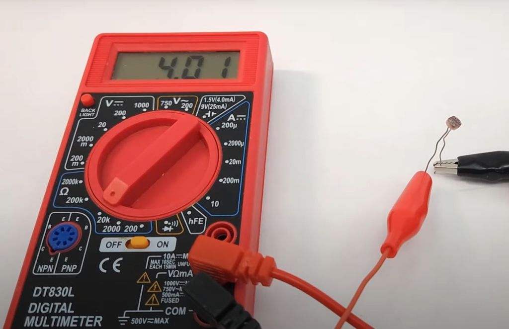
14. How can the resistance of a photoresistor be measured in an Arduino circuit?
The resistance of a photoresistor can be indirectly measured in an Arduino circuit by creating a voltage divider circuit with a known resistor (e.g., 10kΩ). By reading the voltage across the LDR-resistor junction using an analog input pin on the Arduino, you can calculate the LDR’s resistance using Ohm’s Law.
15. What are the disadvantages of a photoresistor?
Some disadvantages of photoresistors (LDRs) include:
- Slow response time to changes in light levels;
- Limited spectral sensitivity (usually sensitive to visible light);
- Susceptibility to temperature variations;
- Limited dynamic range compared to other light sensors
- Degradation over time due to exposure to light;
16. How does a photoresistor change resistance?
A photoresistor changes its resistance based on the intensity of incident light. When exposed to more light, the resistance of the photoresistor decreases, allowing more current to flow through it. Conversely, in low light conditions, the resistance of the photoresistor increases, reducing the current flow.
17. How sensitive is a photoresistor?
The sensitivity of a photoresistor varies depending on its material, design, and the specific wavelength of light it is designed to detect. Photoresistors can be highly sensitive to changes in light, making them suitable for many light-sensing applications. However, their sensitivity can be adjusted or optimized by selecting the appropriate resistor values in the voltage divider circuit.
18. What is the range of the Arduino photoresistor?
The range of an Arduino photoresistor, in terms of the light levels it can detect, depends on the specific LDR used and the circuit design. In typical applications, an LDR can detect light levels ranging from very low (dark) to well-lit conditions, making them suitable for various light-controlled projects. The exact range may vary based on the LDR’s datasheet specifications.
Useful Video: How to Use a Photoresistor (Light Sensor) with Arduino (Lesson #27)
References:
- https://www.instructables.com/How-to-use-a-photoresistor-or-photocell-Arduino-Tu/
- https://www.circuitbasics.com/how-to-use-photoresistors-to-detect-light-on-an-arduino/
- https://www.ardumotive.com/how-to-use-a-photoresistor-en.html
- https://linuxhint.com/photoresistor-ldr-with-arduino-uno/
- https://www.learnrobotics.org/blog/light-following-arduino-robot-using-photoresistors/
- https://electropeak.com/learn/interfacing-photoresistor-ldr-sensor-with-arduino/