In our increasingly digital world, mastering the interface between hardware and software is a skill of growing importance. This article will delve into the fascinating subject of how to use a water level sensor with an Arduino. From detecting water leakage to measuring the water level in various contexts, this tool offers a wide array of practical applications.
We’ll guide you through the process with easy-to-follow steps, making this knowledge accessible whether you’re a DIY hobbyist, an engineer, or a curious learner. Get ready to immerse yourself in the dynamic intersection of technology and everyday life.
What Is A Water Level Sensor?
Water level sensors come in different types and designs, each utilizing various sensing principles to achieve accurate measurements. Some common types of water level sensors include capacitance sensors, conductivity sensors, ultrasonic sensors, and pressure sensors.
These sensors can be categorized based on their working principles:
- Capacitance-Based Sensors: Capacitance-based water level sensors rely on changes in capacitance when the sensor’s electrodes or probes come into contact with water. As the water level rises or falls, the capacitance between the probes changes, and this change is used to determine the water level;
- Conductivity-Based Sensors: Conductivity-based sensors measure the electrical conductivity of water. Water is a conductor of electricity, so as the sensor’s probes are immersed in water, the resistance between them decreases. This change in resistance is used to infer the water level;
- Ultrasonic Sensors: Ultrasonic water level sensors use ultrasonic waves to measure the distance to the water’s surface. These sensors emit a sound wave and measure the time it takes for the wave to bounce back, allowing for precise determination of the water level;
- Pressure Sensors: Pressure-based water level sensors work by measuring the pressure exerted by the water at a specific depth. As the water level rises or falls, the pressure on the sensor’s diaphragm changes, and this variation is used to calculate the water level;
The choice of water level sensor type depends on the specific application requirements, such as the nature of the liquid being measured, the accuracy needed, environmental conditions, and cost considerations.
Water level sensors are vital components in a wide range of applications, including:
- Industrial Tank Monitoring: They are used to monitor and manage the levels of various liquids in industrial tanks, ensuring optimal operation and preventing overflows or shortages;
- Agricultural Irrigation: Water level sensors help automate irrigation systems by ensuring that crops receive the appropriate amount of water;
- Environmental Monitoring: These sensors are employed to measure water levels in rivers, lakes, and reservoirs for flood prediction, drought monitoring, and environmental research;
- Aquarium Management: Water level sensors are used to maintain proper water levels in aquariums, preventing damage to aquatic life due to water evaporation;
- Home Automation: In home automation systems, they are integrated into smart devices to control water levels in tanks, basements, and other areas prone to flooding;
- Weather Stations: Water level sensors are crucial components of weather stations, providing data on rainfall levels for meteorological purposes [2];
How Can Arduino Help To Use A Water Level Sensor?
Hardware Outline of the Water Level Sensor
Water level sensors come in different types and designs, but they all share a common purpose: to detect the presence and depth of water.
Here are some common hardware components found in water level sensors:
- Probes or Electrodes: Probes are the primary components of a water level sensor that come into direct contact with the liquid. These probes are typically made of materials that are corrosion-resistant, such as stainless steel or copper;
- Circuitry: Water level sensors include circuitry that processes the signals received from the probes and converts them into a usable form, often analog or digital signals;
- Housing: The housing of a water level sensor is designed to protect the internal components from environmental factors like moisture and chemicals. It ensures the sensor’s durability and longevity;
- Connectors: Water-level sensors typically have connectors for interfacing with external devices, such as microcontrollers like Arduino [3];
Working Principle of the Water Level Sensor
To understand how water level sensors work, it’s essential to grasp their underlying principles.
Water level sensors use a variety of methods to detect water levels, with the most common ones being:
1. Capacitance Sensing
Capacitance-based water level sensors work on the principle of changes in capacitance. When the sensor’s probes come into contact with water, the capacitance between the probes changes. This change is proportional to the water level and is used to determine the depth.
2. Conductivity Sensing
Conductivity-based sensors rely on the electrical conductivity of water. As water is a conductor of electricity, the sensor measures the resistance between its probes. When immersed in water, the resistance decreases, and this change is used to infer the water level.
3. Ultrasonic Sensing
Ultrasonic water level sensors use ultrasonic waves to measure the distance to the water’s surface. By sending out a sound wave and measuring the time it takes for the wave to bounce back, these sensors can accurately determine the water level.
4. Pressure Sensing
Pressure-based sensors work by measuring the pressure exerted by the water at a specific depth. As the water level rises or falls, the pressure changes and this variation is used to calculate the water level.
Pin Description of the Water Level Sensor:
1. VCC (Voltage Supply)
The VCC pin is used to provide power to the water level sensor. It typically operates within a specified voltage range, which can vary depending on the sensor model. It’s essential to connect this pin to the appropriate voltage source to ensure proper sensor operation [4].
2. GND (Ground)
The GND pin is the ground or common reference point for the sensor’s circuitry. It should be connected to the ground (0V) of the power supply or microcontroller to complete the electrical circuit.
3. Signal Output
The signal output pin is where the sensor provides the measured data, typically in the form of analog or digital signals. The type of signal (analog or digital) and its voltage levels may vary between sensor models, so it’s essential to consult the sensor’s datasheet or documentation for specific details.
4. Sensing Probes
The sensing probes, also known as electrodes, are the components of the sensor that come into contact with the liquid being measured. The number and arrangement of probes may vary among sensor designs. In some cases, there may be separate pins for each probe.
Interfacing a Water Level Sensor with Arduino:
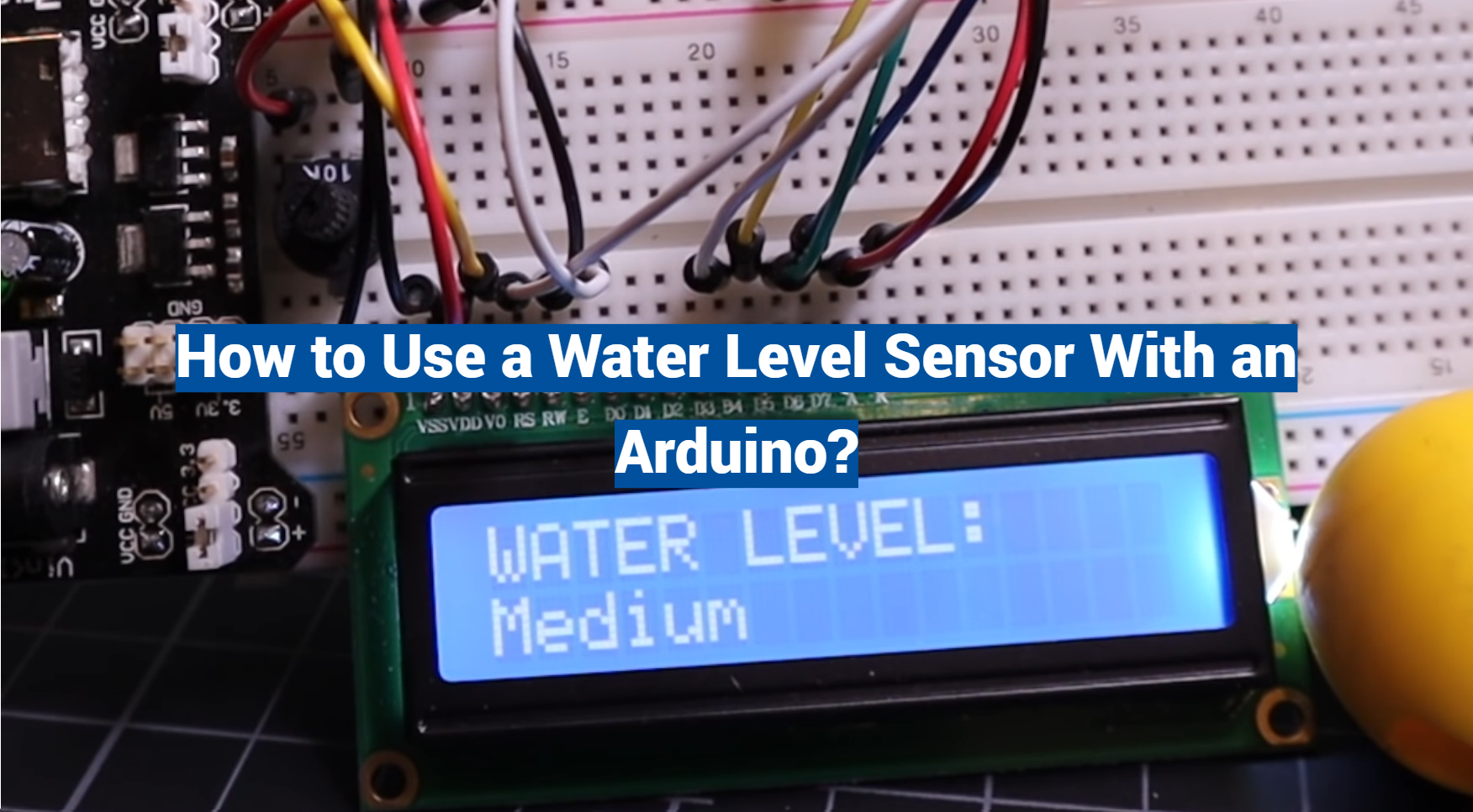
Components Needed
- Arduino board (e.g., Arduino Uno, Arduino Nano);
- Water level sensor;
- Jumper wires;
- Breadboard (optional);
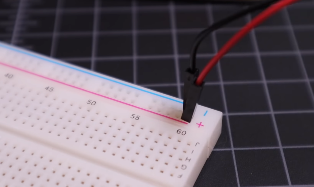
Wiring the Water Level Sensor
To interface the water level sensor with Arduino, follow these general steps:
- Connect the VCC pin of the water level sensor to the 5V output of the Arduino board;
- Connect the GND pin of the water level sensor to any of the Arduino’s GND (ground) pins;
- Connect the signal output pin of the water level sensor to one of the Arduino’s analog input pins (e.g., A0) if the sensor provides an analog signal. For digital output sensors, connect it to a digital input pin (e.g., D2) [5];
Writing Arduino Code
Once the hardware is connected, you’ll need to write Arduino code to read and interpret the data from the water level sensor.
Below is a basic example of Arduino code for reading data from an analog water level sensor:
const int sensorPin = A0; // Analog input pin for the water level sensor
int sensorValue = 0; // Variable to store the sensor reading
void setup() {
Serial.begin(9600); // Initialize serial communication
}
void loop() {
// Read the analog value from the sensor
sensorValue = analogRead(sensorPin);
// Convert the analog value to a water level percentage (adjust this based on your sensor)
int waterLevelPercentage = map(sensorValue, 0, 1023, 0, 100);
// Print the water level percentage to the serial monitor
Serial.print(“Water Level Percentage: “);
Serial.print(waterLevelPercentage);
Serial.println(“%”);
delay(1000); // Delay for one second before taking the next reading
}
In this code, we read the analog signal from the water level sensor, map it to a percentage scale, and then print the water level percentage to the serial monitor. You can customize the code based on your specific sensor’s characteristics and your project’s requirements [6].
Step-by-Step Guide for Calibrating the Sensor:
Calibrating a water level sensor is essential to ensure its accuracy in measuring water levels.
Here’s a step-by-step guide on how to calibrate a typical water level sensor:
Step 1: Gather Your Equipment:
- Water level sensor;
- Arduino board (e.g., Arduino Uno);
- A container with clear and easily measurable water levels;
- Jumper wires;
- A stable power supply for the Arduino;
- Computer with Arduino IDE installed;
Step 2: Connect the Sensor
Follow the manufacturer’s instructions or datasheet to connect the water level sensor to the Arduino board. Typically, you’ll need to connect the sensor’s VCC, GND, and signal pins to the appropriate Arduino pins.
Step 3: Upload Blank Sketch
Upload a blank sketch (empty setup and loop functions) to the Arduino board to ensure that it’s powered but not interfering with the calibration process.
Step 4: Prepare the Water Container
Fill the container with water, ensuring that you have a range of water levels to work with during calibration. You should have a minimum of three different water levels: low, medium, and high.
Step 5: Calibrate the Low Water Level:
- Start with the water level sensor submerged in the container at its lowest level (e.g., low water mark);
- Record the sensor’s reading (analog or digital value) corresponding to this low water level;
- This recorded value represents the sensor’s output when it detects the low water level;
Step 6: Calibrate the Medium Water Level:
- Raise the water level in the container to a medium level;
- Record the sensor’s reading at this medium water level;
- This recorded value represents the sensor’s output when it detects the medium water level;
Step 7: Calibrate the High Water Level:
- Raise the water level in the container to its highest point;
- Record the sensor’s reading at this high water level
- This recorded value represents the sensor’s output when it detects the high water level [7];
Step 8: Create a Calibration Table
Based on the recorded values for low, medium, and high water levels, create a calibration table or formula to map sensor readings to actual water levels. You can use linear interpolation to estimate the water level at any reading within the sensor’s range.
Step 9: Test and Verify
Test the calibrated sensor by placing it in various water levels and comparing its readings with the expected values. Make adjustments to the calibration if necessary until the readings are accurate and consistent.
Step 10: Document the Calibration
Record the calibration parameters, including the low, medium, and high water level readings, and the calibration equation if applicable. Store this information for future reference.
Interfacing Diagram for Connecting the Sensor with Arduino
Here’s a simplified interfacing diagram to connect a water level sensor to an Arduino board:
Sensor Arduino
+—–+ +——+
| | | |
| VCC |—VCC—| 5V |
| GND |—GND—| GND |
| OUT |—Analog-| A0 |
| | | |
+—–+ +——+
- Connect the sensor’s VCC pin to the Arduino’s 5V power supply;
- Connect the sensor’s GND pin to any GND (ground) pin on the Arduino;
- Connect the sensor’s OUT (signal) pin to one of the Arduino’s analog input pins, such as A0;
Code Explanation for Arduino to Interface with the Sensor
Below is a basic Arduino code snippet to interface with a water level sensor and read analog values from it:
const int sensorPin = A0; // Analog input pin for the water level sensor
int sensorValue = 0; // Variable to store the sensor reading
void setup() {
Serial.begin(9600); // Initialize serial communication for debugging
}
void loop() {
// Read the analog value from the sensor
sensorValue = analogRead(sensorPin);
// Print the sensor reading to the serial monitor
Serial.print(“Sensor Reading: “);
Serial.println(sensorValue);
delay(1000); // Delay for one second before taking the next reading
}
In this code:
- We define sensorPin as the analog input pin connected to the sensor (A0 in this case);
- In the setup function, we initialize serial communication for debugging purposes;
- In the loop function, we continuously read the analog value from the sensor using analogRead and print it to the serial monitor [8];
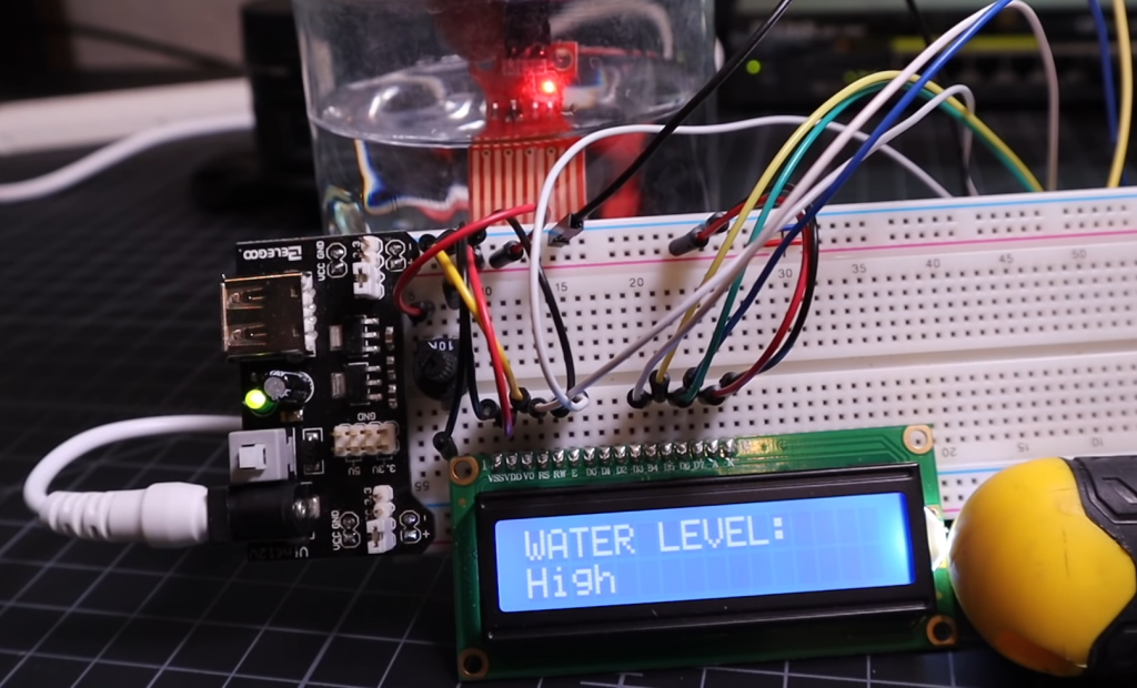
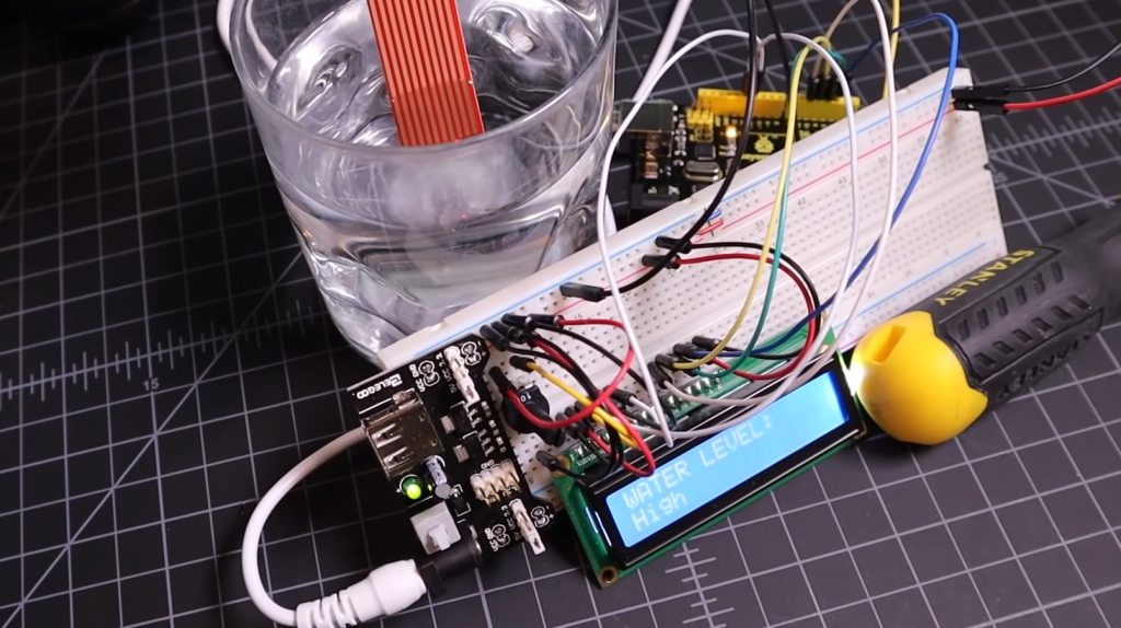
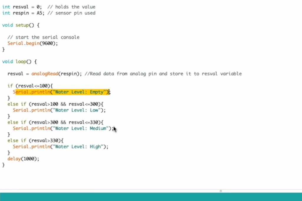
Explanation of the Water Level Indicator Output
For example, an analog water level sensor may provide readings in the range of 0 to 1023, with 0 indicating the lowest water level and 1023 indicating the highest water level [9]. A digital sensor might output a logic high (1) when the water level is above a certain threshold and a logic low (0) when it’s below that threshold.
The water level indicator output is crucial for making decisions or triggering actions based on the water level. By interpreting this output, you can determine whether the water level is within a safe range, needs attention, or requires specific actions.
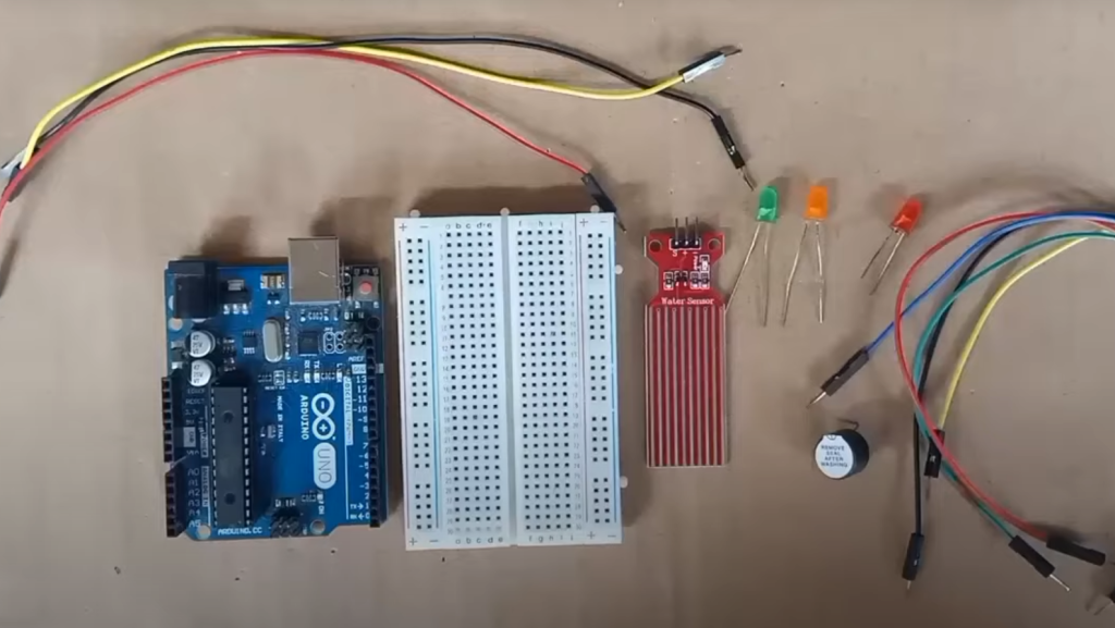
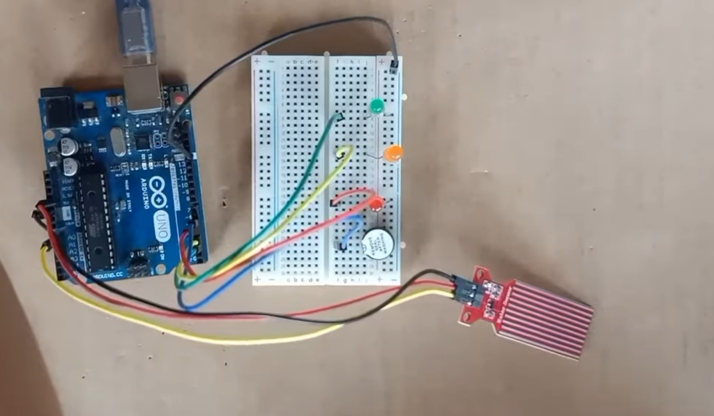
Understanding the LED Indications for Different Water Levels
In some water level sensor applications, LED indicators are used to visually represent the water level to users. These LED indicators can provide valuable information about the water level at a glance.
Here’s a typical LED indication scheme for different water levels:
- Low Water Level: When the water level is low or below a safe threshold, a specific LED or set of LEDs may remain off or emit a dim light. This indicates that the water level needs attention, such as refilling;
- Medium Water Level: As the water level rises to a medium level, a different LED or group of LEDs may turn on or emit a brighter light. This signals that the water level is within an acceptable range;
- High Water Level: When the water level reaches a high level, another LED or set of LEDs may turn on at full brightness or start blinking. This indicates that the water level is at a critical point, and immediate action may be required, such as draining or shutting off a water source;
These LED indications provide a quick and intuitive way for users to assess the water level status without having to read numerical values. They are particularly useful in applications like aquariums, home water tanks, and industrial processes where monitoring water levels is essential for safety and proper functioning.
How to Test If The Water Level Sensor Works?
Testing a water level sensor to ensure it works correctly is a crucial step before deploying it in any application.
Here is a step-by-step guide on how to test if the water level sensor works:
Materials Needed:
- Water level sensor;
- Arduino board (e.g., Arduino Uno);
- Jumper wires;
- A container of water;
- Computer with Arduino IDE installed (for programming);
Procedure:
1. Prepare Your Environment:
- Set up your workspace with the Arduino board, jumper wires, and a computer;
- Make sure you have a container of water ready for testing. The water should be deep enough to cover the sensor probes when you immerse it [10];
2. Connect the Water Level Sensor to Arduino:
- Follow the manufacturer’s instructions or datasheet to connect the water level sensor to the Arduino board;
- Typically, you’ll connect the VCC pin to 5V, the GND pin to GND, and the signal pin to an analog or digital input pin on the Arduino;
3. Upload a Test Sketch:
- Open the Arduino IDE on your computer;
- Write or upload a simple test sketch to read data from the water level sensor;
Here’s an example sketch for reading analog data from an analog water level sensor connected to analog pin A0:
const int sensorPin = A0; // Analog input pin for the water level sensor
int sensorValue = 0; // Variable to store the sensor reading
void setup() {
Serial.begin(9600); // Initialize serial communication for debugging
}
void loop() {
// Read the analog value from the sensor
sensorValue = analogRead(sensorPin);
// Print the sensor reading to the serial monitor
Serial.print(“Sensor Reading: “);
Serial.println(sensorValue);
delay(1000); // Delay for one second before taking the next reading
}
Upload the sketch to your Arduino board.
4. Open the Serial Monitor:
In the Arduino IDE, go to “Tools” > “Serial Monitor” to open the serial monitor window.
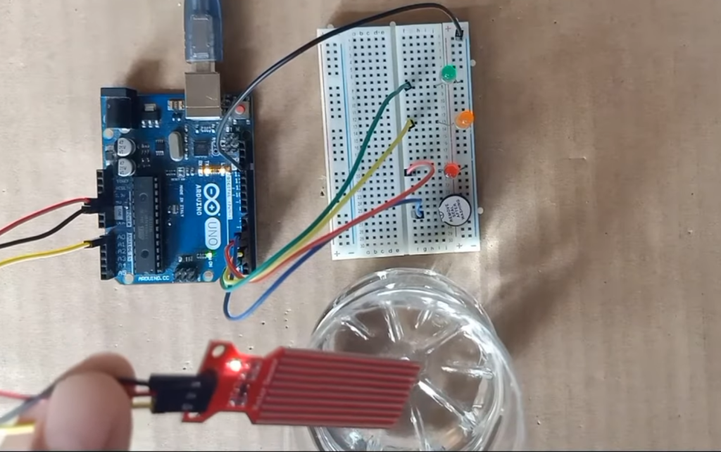
5. Immerse the Sensor:
Carefully immerse the water level sensor into the container of water, ensuring that the sensor probes are fully submerged.
6. Observe the Readings:
In the serial monitor, you should see the sensor readings displayed. The readings may vary depending on the water level.
As you immerse the sensor further into the water, the readings should change accordingly. If the sensor is working correctly, the readings will respond to changes in water level.
7. Verify Sensor Operation:
Gradually raise and lower the water level in the container to confirm that the sensor accurately detects these changes.
Pay attention to the readings in the serial monitor and ensure that they correspond to the expected water level changes.
8. Calibration (if necessary):
If you notice significant discrepancies between the sensor readings and actual water levels, you may need to calibrate the sensor.
9. Final Checks:
Check for any signs of malfunction or erratic behavior in the sensor during the testing process.
Ensure that the sensor reliably responds to changes in water level and provides consistent readings.
10. Documentation:
Record the sensor’s performance during testing, including any calibration adjustments made, and store this information for future reference.
FAQ:
1. What is the ideal calibration range for the water level sensor?
The ideal calibration range for a water level sensor depends on the specific application and the expected range of water levels you need to measure.
To determine the ideal calibration range:
- Identify the minimum and maximum water levels you expect to encounter in your application;
- Set your reference points for calibration within this range. For better accuracy, include at least three reference points: low, medium, and high;
- Calibrate the sensor to accurately measure water levels within this range [11];
Make sure the sensor’s operating range matches your application requirements, and the calibrated range covers the expected variations in water levels.
2. Can I use the water level indicator for other liquids besides water?
Yes, water level sensors can be used for liquids other than water, depending on the sensor’s compatibility with the specific liquid. Some sensors are designed to work with a wide range of liquids, while others are optimized for water. Ensure that the sensor’s materials and design are suitable for the target liquid, and consider calibrating it for accurate measurements in that specific liquid.
3. How long does the water level sensor last before requiring replacement?
The lifespan of a water level sensor can vary widely based on several factors, including the sensor’s quality, environmental conditions, and usage. High-quality sensors used in controlled environments can last for many years.
However, sensors exposed to harsh conditions or corrosive liquids may have a shorter lifespan. Regular maintenance and careful handling can extend the sensor’s life. In general, a well-maintained water level sensor can last several years to a decade or more.
4. How do you connect a water level sensor to an Arduino?
To connect a water level sensor to an Arduino, follow these steps:
- Identify the sensor’s VCC (power), GND (ground), and OUT (signal) pins;
- Connect the VCC pin to the Arduino’s 5V output;
- Connect the GND pin to one of the Arduino’s GND pins;
- Connect the OUT pin to an analog or digital input pin on the Arduino, depending on the sensor type;
- Upload a code sketch to read and interpret the sensor’s output on the Arduino [12];
5. How to use a soil moisture sensor with Arduino?
To use a soil moisture sensor with an Arduino, follow these steps:
- Connect the sensor to the Arduino, typically using digital or analog pins for data;
- Write code to read the sensor’s output;
- Calibrate the sensor if necessary for your specific soil type and application;
- Use the sensor readings to determine soil moisture levels;
- Implement control logic or data logging based on the moisture levels;
6. How do you hook up a water level sensor?
Hooking up a water level sensor involves connecting it to a microcontroller like Arduino or a data acquisition system. Typically, you connect the sensor’s power (VCC), ground (GND), and signal (OUT) pins to the corresponding pins on the microcontroller. The exact connections may vary depending on the sensor model and type.
7. How to use a water pump with Arduino?
To use a water pump with an Arduino, you can follow these general steps:
- Connect the water pump to the Arduino using a suitable driver or relay module;
- Write Arduino code to control the pump, specifying when it should turn on or off based on sensor readings or other criteria;
- Upload the code to the Arduino;
- Test and verify the pump’s operation by running the code;
8. Can Arduino detect water?
Arduino itself cannot directly detect water. However, it can interface with various water sensors, such as water level sensors or water leakage sensors, to detect the presence or absence of water. These sensors provide feedback to the Arduino, which can then trigger actions or alerts based on the sensor’s readings.
9. What is a moisture sensor in Arduino?
A moisture sensor in Arduino is typically a soil moisture sensor that measures the moisture content of soil or other materials. These sensors are used in applications like plant watering systems, where they help determine when to water plants based on soil moisture levels.
10. What voltage is needed for a soil moisture sensor Arduino?
Most soil moisture sensors compatible with Arduino operate at 5 volts. Therefore, you should provide 5 volts from the Arduino’s 5V output or an external power source to the sensor’s VCC pin [13].
11. How to connect sensors to Arduino?
Connecting sensors to an Arduino generally involves identifying the sensor’s power, ground, and signal pins and connecting them to the corresponding pins on the Arduino. The exact wiring and code will depend on the sensor type and model. Always refer to the sensor’s datasheet or manufacturer’s instructions for specific guidance.
12. Where do you put a water sensor?
The placement of a water sensor depends on its purpose:
- For flood detection, place the sensor in low-lying areas prone to flooding;
- In-home water tanks, position the sensor at a level corresponding to the desired water level;
- In aquariums, submerge the sensor to monitor water levels for aquatic life;
- For leak detection, place sensors near potential sources of water leaks, such as pipes or appliances;
13. How accurate is the Arduino water level sensor?
The accuracy of an Arduino water level sensor can vary based on the sensor’s quality, type, and calibration [14]. High-quality sensors with proper calibration can provide reasonably accurate readings within a specific range. However, for critical applications, additional testing and calibration may be necessary to achieve a higher level of accuracy.
14. Are water sensors waterproof?
Water sensors designed for detecting water or moisture are typically waterproof or water-resistant to varying degrees. However, the level of water resistance can vary between different sensor models. Always check the sensor’s specifications to determine its level of waterproofing and suitability for your application.
Useful Video: How to use water level sensor with Arduino Uno
References:
- https://lastminuteengineers.com/water-level-sensor-arduino-tutorial/
- https://circuitdigest.com/microcontroller-projects/interfacing-water-level-sensor-with-arduino
- https://arduinogetstarted.com/tutorials/arduino-water-sensor
- https://www.aranacorp.com/en/using-a-water-level-sensor-with-arduino/
- https://www.instructables.com/How-to-use-a-Water-Level-Sensor-Arduino-Tutorial/
- https://robu.in/water-level-indicator-interfacing-with-arduino-connection-and-code/
- https://srituhobby.com/water-level-sensor-tutorial-how-to-use-water-level-sensor/
- https://robocraze.com/blogs/post/water-level-indicator-interfacing-water-level-sensor-with-arduino
- https://mytectutor.com/water-level-sensor-with-arduino/
- https://www.thegeekpub.com/236571/arduino-water-level-sensor-tutorial/
- https://electropeak.com/learn/water-level-sensor-with-arduino-how-to-use-pinout-code/
- https://peppe8o.com/water-level-sensor-with-arduino-uno-wiring-and-code-description/
- https://microcontrollerslab.com/water-level-sensor-interfacing-arduino/
- https://maker.pro/arduino/projects/ultrasonic-arduino-water-level-indicator